Product Combination: SPU232.2 Industrial-grade Single Processor Unit +
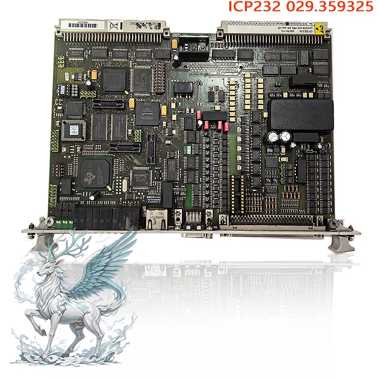
ICP232 Synchronous Pulse Processing Unit
Brand Affiliation: ALSTOM (formerly Converteam; part of the lineage
preceding Hitachi Energy)
Associated System: Semipol D3.1 Generator Excitation Regulator. The
complete hardware configuration—comprising the SPU232.2, ICP232, PIB101
measurement board, and DIZ232 digital input board—forms the complete excitation control chain.
Note: Online information often contains inaccuracies regarding module
classification, such as misidentifying the ICP232 as a standard analog output
board or oversimplifying the SPU232.2 as a generic DCS main control board. In
the actual architecture of the Semipol D3.1 excitation cabinet, the SPU232.2
serves as the computational core of the entire excitation system, while the
ICP232 acts as the interface unit for phase-locked synchronization and pulse
driving. These two boards work in tandem to execute generator AVR (Automatic
Voltage Regulation) and thyristor trigger control. They are core components for
excitation system retrofitting and spare part replacement in thermal,
hydroelectric, and gas-fired power units.
I. Operating Principle of the Combination
As the single-processor main control unit, the SPU232.2 performs data
aggregation and computation for the entire system via the rack backplane bus and
an isolated CAN bus. Analog signals—such as generator terminal voltage, rotor
current, and stator current—are fed into the PIB101 measurement board for signal
conditioning, while digital signals (e.g., circuit breaker status and excitation
switching commands) are acquired by the DIZ232 digital input board; all acquired
data is transmitted to the SPU232.2 via the backplane. The boards scan the input
signals at fixed intervals, performing analog-to-digital conversion and noise
filtering. They execute built-in excitation PID regulation algorithms and
various limiting/protection models to calculate thyristor trigger angle
commands, which are then sent to the ICP232 module. The ICP232 receives firing
angle commands from the SPU232.2 while independently acquiring synchronization
voltage signals from the generator terminals via potential transformers (PTs).
The module features a built-in hardware phase-locked loop (PLL) that
continuously tracks the phase and frequency of the terminal voltage and
independently resolves the synchronization phase, thereby avoiding the
consumption of SPU main control processing resources. Based on the received
firing angle commands, it precisely calculates the thyristor firing moments and
generates multiple isolated drive pulse signals for the thyristors in the
excitation power cabinet. Internally, the module comprises distinct zones for
signal isolation, PLL computation, pulse driving, and hardware fault detection;
synchronization signals undergo level conversion via high-voltage isolation
circuits to block high-voltage interference from the power side. Each pulse
channel performs real-time verification of pulse width and amplitude; if pulse
loss, distortion, or abnormal feedback from the power circuit is detected, the
hardware circuitry immediately inhibits pulse output and transmits fault codes
and phase snapshots back to the SPU232.2 via the backplane bus.
The two boards maintain clock synchronization and aligned control timing,
with each equipped with an independent hardware watchdog. The SPU232.2 watchdog
monitors the execution status of the main control program, while the ICP232
watchdog ensures the safety of the pulse output link. Should the program of
either module crash or communication fail, safety actions are rapidly executed
to prevent erroneous excitation triggering. The system employs a hierarchical
diagnostic mechanism: the SPU handles global fault logic assessment and event
logging, while the ICP manages front-end hardware protection on the pulse side;
fault information is centrally uploaded to the supervisory system via the
CAN2.0B bus.
II. Functions of the Combined System
Generator Automatic Voltage Closed-Loop Control: The SPU232.2 executes core
control algorithms, including AVR voltage regulation, reactive power regulation,
and limits for over-excitation, under-excitation, and stator current. The ICP232
handles phase synchronization and the precise output of thyristor firing pulses.
Together, they stabilize the generator terminal voltage and control the unit's
reactive power output. Synchronization Signal Acquisition and Pulse Drive
Conversion: The ICP232 acquires synchronization voltage from the generator
terminals, providing the phase reference required for grid connection, field
flashing, and field de-excitation. It converts angle commands issued by the main
controller into isolated pulse signals capable of driving the power rectifier
bridge, serving as a critical interface between the low-voltage control unit and
the high-voltage power cabinet.
Hierarchical Fault Protection and Interlock Control: The SPU232.2 handles
system-level binary interlocks, fault logic assessment, and system trip
protection. The ICP232 implements hardware-level front-end protection for pulse
and synchronization signal circuits; in the event of faults such as pulse line
breakage or loss of synchronization signals, it prioritizes pulse blocking,
thereby establishing a two-tier protection mechanism to prevent fault
propagation.
Bus Data Management and Fault Traceability: The SPU232.2 manages the
internal CAN bus network, aggregating real-time data from I/O boards,
measurement boards, and ICP232 modules, and uploading operating parameters and
timestamped fault events to the host computer. The ICP232 records snapshots of
pulse channel and phase anomalies, which are passed to the SPU for centralized
storage to facilitate subsequent fault analysis.
Coordinated Control of Excitation Engagement and Disengagement: It
coordinates the logic for field flashing, de-excitation, and excitation
switching. By operating in concert during grid connection, disconnection, and
fault conditions, it ensures the generator excitation system transitions
smoothly across various operating states.
III. Advantages of the Combined Product
Hardware-Software Functional Partitioning (Balancing Real-time Performance
and Stability): The SPU focuses on excitation regulation algorithm computations,
while the ICP implements phase-locking and pulse generation via hardware. This
separation of computing tasks ensures that fluctuations in the main controller's
computational load do not affect pulse phase accuracy, thereby meeting the
rigorous timing requirements for generator grid connection and precise reactive
power regulation. Layered isolation and two-level safety protection:
Synchronization and pulse-drive channels utilize independent electrical
isolation to block strong electromagnetic interference caused by the switching
of thyristors on the power side; dual protection combining software safeguards
and hardware pulse blocking ensures faster response times (via hardware
blocking) compared to software-only methods, thereby reducing the risk of
excitation control loss.
Weather-resistant design for power plant environments: Both PCBs feature
conformal coating and utilize industrial-grade, wide-temperature-range
components; the design withstands the dust, humidity, and vibration typical of
power plant cabinets, supporting continuous 24/7 operation.
.jpg)
Native compatibility within the series for easy spare part replacement: The
SPU232.2 is backward compatible with the SPU232.1; the ICP232 backplane
interface and bus protocols fully match the Semipol D3.1 series, allowing for
spare part replacement in older units without extensive rewiring of the
cabinet—only firmware version verification is required.
Granular channel diagnostics: The SPU monitors overall system status, while
the ICP pinpoints faults in individual pulse or synchronization channels,
distinguishing between main control faults, pulse circuit faults, and power
cabinet faults; this significantly reduces on-site troubleshooting and downtime
for maintenance.
Isolated CAN2.0B bus communication: Features magnetically isolated CAN bus
communication with rates up to 1 Mbps and high interference immunity, ensuring
stable data exchange between modules and with the upper-level monitoring system,
even in the high-electromagnetic-noise environments of power plants.
IV. Operational Procedures (Installation, Power-up & Commissioning,
Spare Part Replacement, and Operational Precautions)
1. Pre-installation checks
Power down the entire unit and disconnect all AC and DC power supplies to
the excitation system; wait for the power cabinet's energy storage capacitors to
fully discharge; use a multimeter to verify the backplane power terminals and
confirm the absence of residual voltage. Inspect the SPU232.2 and ICP232 boards:
ensure the PCBs show no signs of burning or corrosion, the gold fingers are free
of oxidation, and the terminals are secure. Verify that the model and serial
numbers of both boards match the original spare parts. Clean dust from the rack
slots and inspect the backplane pins to ensure they are not bent or deformed.
Position the associated PIB101 measurement board and DIZ232 digital input board;
cross-reference the wiring layout for the backplane bus, synchronization voltage
cables, and pulse output cables against the schematics. Do not insert or remove
any modules while the system is powered.
2. Rack Installation
Smoothly slide the SPU232.2 and ICP232 boards into their respective slots
along the cabinet guide rails. Apply even pressure to the front panels to ensure
the gold fingers make full contact with the backplane, then tighten the panel
mounting screws to prevent poor contact caused by unit vibration. Connect the
backplane bus, CAN communication lines, synchronization voltage signal lines,
and pulse output cables (to the power cabinet). Use single-point grounding for
all shielded cables; avoid multi-point grounding to prevent ground potential
interference. Check the DIP switch settings on the back of the boards to ensure
the bus addresses match the original system configuration.
3. Power-up and Commissioning Steps
1) After verifying all wiring, confirm the correct correspondence between
the synchronization voltage range, pulse output connections, and thyristor
circuits; 2) Apply auxiliary power to the cabinet, observe that the board power
indicators remain steadily lit, and wait for the modules to initialize. A steady
flashing of the RUN LED on the SPU232.2 and ICP232 indicates a successful
startup; if the FAULT LED on any module illuminates, immediately cut off power
to inspect backplane connections, DIP switch settings, and wiring. 3) Use the
supplied debugging software to connect to the SPU232.2 via the CAN bus; read the
firmware versions and hardware IDs of both the SPU and ICP boards, and confirm
that the firmware versions are compatible with the unit's excitation program. 4)
Static no-load test: With the unit not yet excited, energize the system and
monitor the acquired generator terminal voltage, phase, and frequency data to
ensure there are no synchronization loss alarms; issue firing angle commands and
monitor the ICP pulse output channels to verify correct pulse timing and width;
simulate synchronization signal loss and pulse channel faults to verify that the
ICP hardware pulse blocking function operates correctly and that fault signals
are successfully transmitted to the SPU. 5) Unit no-load excitation
commissioning: Activate excitation and slowly ramp up the generator terminal
voltage; observe that the pulse phase tracks the voltage change smoothly without
pulse jitter or loss alarms; verify the operation of various excitation limiting
logic functions and ensure that SPU output commands are stably transmitted to
the ICP. 6) Unit on-load integrated testing: Connect the unit to the grid and
apply load; test regulation response across various reactive power ranges to
ensure no abnormal system alarms occur; upon completion of commissioning, export
all fault event records and create a full backup of the unit's excitation
parameters for archiving.
.jpg)
4. Routine Operation, Maintenance, and Spare Parts Replacement
Perform routine inspections by checking the RUN and FAULT LEDs on the
SPU232.2 and ICP232 panels; periodically read board diagnostic information and
historical alarm codes via the supervisory monitoring system. In the event of a
module failure, execute the unit shutdown procedure, disconnect the main power
supply to the excitation cabinet, wait for the power capacitors to fully
discharge, and then remove the faulty board. After the new spare parts are
installed, verify the firmware version, bus address, and wiring; complete the
static checks and no-load commissioning; and confirm that the entire excitation
system is functioning correctly before placing the unit into operation.
5. Safety Prohibitions
Do not insert or remove SPU232.2 or ICP232 boards while the power is on; do
not touch synchronization input terminals or pulse output terminals before
capacitors have fully discharged; do not arbitrarily modify excitation
protection settings, pulse output parameters, or phase-lock thresholds; do not
perform online firmware updates on the boards while the unit is carrying a
high-power load; and do not short-circuit pulse output channels during power-on
testing.
Recommended related products:
Kongsberg 303088
Kongsberg 303088G
Kongsberg TRX32
3BHE032025R1101 PCD235
3BHE032025R1101 PCD235
PCD235 3BHE057901R0101
3BHE057901R0101 PCD235
3BHE028915R0101 PCD237A1011
3BHE028915R0101 PCD237A1011
3BHE041343R0102 PCD530A
PPD103B101 3BHE020455R0101
3BHE017628R0002 PPD115
3BHE017628R0102 PPD115
PPD115A102 3BHE017628R0102
PPD117A3011 3BHE030410R3011
3BHE040375R1023 PPD512
PPD512A10-15000 3BHE040375R1023
PPD512A10-454000 3BHE040375R103E
3BHE039724R0C4A PP D513A0C
PP D513 A0C-110440 3BHE039724R0C4A
PPD513 A0E-110110 3BHE039724R0E41
3BHE039724R0E41 PPD513
More......


 ABB
ABB GE
GE HONEYWELL
 TRICONEX
 KONGSBERG
 EMERSON
 FOXBORO
 MOTOROLA
 VIBRO-METER
 ICS TRIPLEX
 WOODWARD
 BENTLY NEVADA
 OTHER
OTHER Home
Home 2026/09/29
 4610
4610