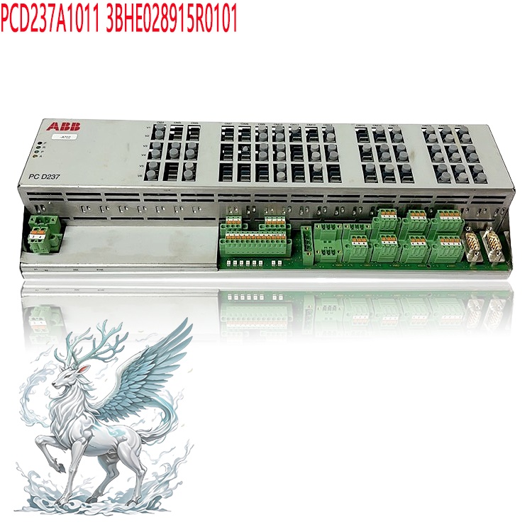
Many products have not yet been listed online; please contact us for more
information.
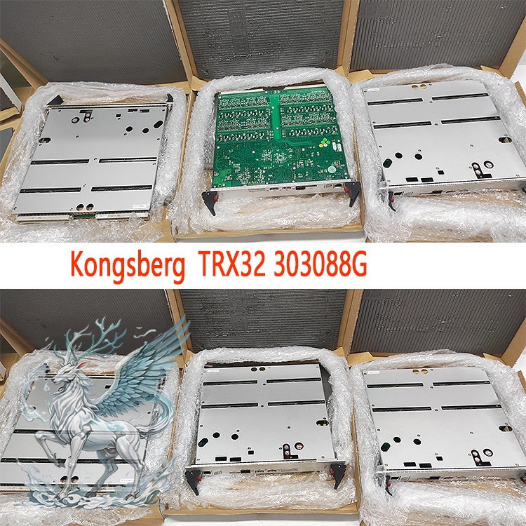
If the product model differs from the displayed image, the model number
takes precedence. Please contact us for specific product photos; we can arrange
for warehouse staff to take and verify images.
We operate 76 shared warehouses globally, so it may sometimes take a few
hours to provide an accurate response; we appreciate your understanding. Rest
assured, we will address your inquiries as quickly as possible.
Alternative names for TRX32:
TRX32 Input/Output Unit
TRX32 Marine Transceiver
TRX32 PCB Module
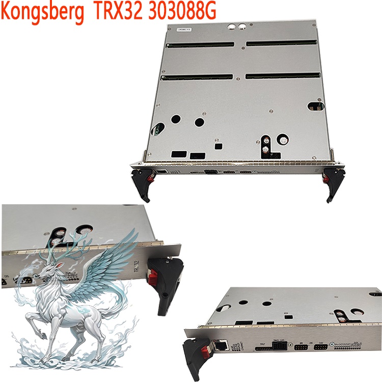
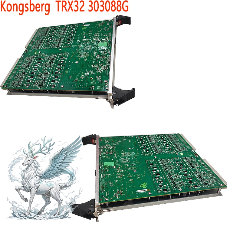
The Kongsberg TRX32 is a core 32-channel, multi-frequency acoustic
transceiver board for the Kongsberg Maritime HiPAP series of high-precision
underwater acoustic positioning systems. Classified as a Line Replaceable Unit
(LRU), it is compatible with the HiPAP 101/351/451/501 (X81 series) acoustic
transceiver housings, allowing for channel capacity expansion by integrating up
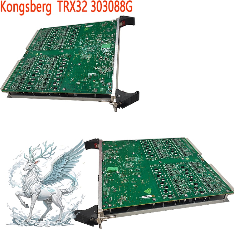
to eight TRX32 boards within a single cabinet. The board features a marine-grade
conformal-coated PCB, a reinforced metal shielding cover, and an extraction
latch. It performs underwater acoustic pulse transmission, echo acquisition, and
digital signal preprocessing, providing the host positioning system with raw
acoustic data—such as range and bearing—relative to underwater transponders. It
serves as critical hardware in the underwater acoustic measurement chain of
offshore dynamic positioning systems.
I. Operating Principle
The TRX32 board integrates 32 independent transmit channels and 32 receive
channels, with each transmit-receive pair corresponding to a specific element in
the transducer array. The operational workflow comprises three main components:
the transmit chain, the receive chain, and digital processing/system synchronization.
Transmit Chain: The HiPAP master control computer sends acoustic pulse
commands, encoding sequences, and operating frequency parameters to the TRX32
via Ethernet. The board's DSP and timing circuitry generate multi-frequency
excitation pulse signals based on configuration settings; these signals pass
through a power amplification circuit to drive the underwater transducer array,
emitting ultrasonic pulses. An onboard high-capacity energy storage capacitor
array ensures stable instantaneous transmission power. The board features two
fuses (F1: 12V/4A; F2: 6V/4A) in the transmission circuit to provide overload
protection and prevent damage to board components caused by transducer short
circuits.
Reception Link: Weak acoustic echoes reflected from seafloor transponders
or beacons are converted into analog electrical signals by the transducer and
fed into the TRX32 reception channel. The signals first enter a low-noise
pre-amplifier for amplification, followed by band-pass filtering to eliminate
marine environmental noise and electromechanical interference from the vessel.
Subsequently, a high-speed ADC digitizes the analog echo signals, performing
sampling, decimation, and preliminary decoding to extract the transponder's
encoded signal and propagation delay information.
.jpg)
Synchronization and Data Upload: The board receives the system's 20MHz
master clock and an external "TXENABLE" trigger synchronization signal, ensuring
strict timing alignment across multiple TRX32 boards and transducer arrays.
Pre-processed digital acoustic measurement data is uploaded via the board's
Ethernet interface to the HiPAP host unit. The host performs beamforming using
multi-channel delay data to calculate the bearing, slant range, and 3D
coordinates of underwater targets (such as ROVs, AUVs, subsea pipelines, and
underwater structures). Finally, the data is fed into the vessel's K-Pos dynamic
positioning system for closed-loop position calculations. The board's front
panel includes indicators for Ethernet link status, data activity, and I/O
status to facilitate real-time local diagnostics; it also provides a P4 external
synchronization interface and P5/P7 debugging serial ports for engineering
commissioning and external trigger connections.
II. Application Fields and
Scenarios
The TRX32 is designed exclusively for use with the Kongsberg HiPAP
high-precision acoustic positioning system. It is primarily deployed on offshore
oil and gas vessels and marine engineering vessels to provide underwater
position references for Dynamic Positioning (DP) systems:
ROV/AUV Tracking and Positioning: Offshore vessels equipped with the HiPAP
system utilize the TRX32 to drive transducers for real-time tracking of
underwater robots (ROVs/AUVs), supporting operations such as subsea pipeline
inspection, wellhead maintenance, and subsea installations.
.jpg)
Underwater Structure Monitoring: Positioning and monitoring of subsea
pipelines, underwater pile foundations, and floating platform mooring lines
using underwater transponders to determine the 3D positions of subsea facilities
and monitor displacement and settlement.
Offshore Dynamic Positioning (DP): Drilling platforms, pipe-laying vessels,
and heavy-lift vessels rely on HiPAP acoustic positioning as a position
reference source for their DP systems. The TRX32 handles acoustic signal
acquisition, ensuring the vessel maintains its position even in environments
where GPS signals are unavailable.
Hydrographic Surveying and Marine Engineering Surveys: Measurement of
underwater beacon arrays and calibration of seabed reference arrays, providing
sub-degree bearing measurement capabilities to meet high-precision marine
surveying requirements.
Equipment Maintenance and Spare Part Replacement: On-site repair of HiPAP
systems; damaged TRX32 cards can be replaced directly without returning the
entire unit to the factory, thereby minimizing offshore downtime.
III. Operating Procedures
Prerequisites: Strictly adhere to the Kongsberg HiPAP original equipment
manufacturer (OEM) maintenance manual. Operations must be performed only by
certified offshore equipment engineers. Hot-swapping (inserting or removing)
cards is prohibited while the vessel is in DP operation mode, except in
emergencies.
(I) Card Removal Procedure
System Preparation: Notify the DP operator to switch the HiPAP system to an
alternative position reference source and isolate the relevant channels in the
X81 transceiver cabinet. Turn off the power supply to the cabinet and wait for
the card's energy-storage capacitors to fully discharge (observing the static
discharge time specified by the OEM).Cable Removal: Disconnect all external
cables attached to the board's front panel—including Ethernet, synchronization
(P4), and debug serial ports (P5/P7)—and label the cables with their
corresponding identifiers.
Unlocking and Extraction: Press the red release knobs on both sides of the
board, operate the upper and lower ejector levers to disengage the board from
the backplane slot, and slide the TRX32 board out steadily and horizontally;
take care to avoid bumping the shielding cover or the capacitor array on the
board.
.jpg)
Storage: Place the removed board into an anti-static bag and store it in a
dry, shock-proof spare parts box; do not stack bare boards directly on top of
one another.
(II) Board Installation Procedure
Anti-static Protection: Wear an anti-static wrist strap; verify that the
spare part model is TRX32 and check the hardware version.
Rail Alignment: Slide the board horizontally into the slot along the rack
rails, ensuring the backplane connectors are aligned; press the ejector levers
on both sides until the board is fully locked and the red locking latches
reset.
Cable Reconnection: Reconnect the Ethernet, external synchronization, and
debug interface cables in the order indicated by the labels.
DIP Switch Configuration: Configure the board ID address using the SW1 and
SW2 DIP switches on the front panel; ensure that addresses do not conflict when
multiple TRX32 boards are installed in the same chassis.
Power-up and Self-test: Power on the cabinet and observe the status of the
power, Ethernet, and I/O indicators on the front panel; access the hardware
diagnostics interface on the HiPAP host computer and perform board
identification, channel self-tests, and transducer circuit tests.
System Calibration: After replacing the board, perform HiPAP acoustic
channel gain and time-delay calibrations, verify that positioning data output is
normal, and switch back to DP online mode.
(III) Routine Online Operations
During normal system operation, engineers may only monitor the TRX32 status
via the host computer—reading channel signal amplitudes, noise levels, board temperatures, supply voltages, and F1/F2 fuse statuses. Remote adjustment of
transmit power, receive gain, and operating frequency parameters is permitted;
however, modifying hardware DIP switch settings while the system is online is
strictly prohibited.
IV. Precautions
1. Electrostatic Protection
The TRX32 integrates numerous precision semiconductor components (such as
DSPs and ADCs) that are highly sensitive to static electricity. All disassembly,
assembly, and testing operations must be performed while wearing a certified
anti-static wrist strap and using a grounded workbench. Touching the pins,
capacitors, or chip areas on the back of the board is prohibited. Anti-static
packaging must be used throughout the transport and storage of spare parts;
handling bare boards in high-static, dry environments is strictly forbidden.
Electrostatic discharge (ESD) can cause latent component damage—faults may not
be immediately apparent but can lead to failure following vibration caused by
sea conditions.
2. Electrical Safety
The board contains high-capacity energy-storage capacitors that retain high
voltage after power-off. You must wait for the specified discharge time after
disconnecting power before removing the board to prevent electric shock or
damage to the backplane interface caused by arcing.
Channel outputs must never be short-circuited while unloaded; damaged or
short-circuited transducer cables can instantly burn out the board's transmit
channels or blow the F1/F2 fuses. Always measure the insulation and impedance of
transducer cables before performing maintenance.
The supply voltage must remain within the rated range specified on the
nameplate. Fluctuations or surges in the ship's power grid can cause DSP reboots
or hardware damage; the power protection module at the cabinet input must be
inspected regularly.
3. Environmental and Mechanical Precautions
The board is a marine rack-mount LRU (Line Replaceable Unit). Although it
features vibration resistance and protective coatings against salt spray and
environmental hazards, it must not be removed from the cabinet and exposed to
the humid, salt-laden air of the deck. Adequate ventilation must be maintained
inside the cabinet, and dust filters must be cleaned regularly to prevent dust
accumulation from causing the board to overheat. Insert and remove the card
horizontally; do not tilt or use force to pry it, as this can bend the backplane
connector pins. Do not remove the metal shielding cover, as it is crucial for
suppressing electromagnetic interference affecting acoustic signals.
4. System and Configuration Risks
Within the same X81 chassis, DIP switch IDs for multiple TRX32 cards must
not be duplicated; ID conflicts prevent the system from recognizing the cards
and cause acoustic channel errors.
Channel calibration must be performed after replacing a card; putting the
system online without doing so introduces ranging and bearing errors, leading to
abnormal DP positioning and compromising vessel operational safety.
The card is a core safety-critical component of the HiPAP system; the use
of non-original firmware or third-party modifications is strictly prohibited, as
incorrect firmware flashing can render the card unusable.
5. Fault and Spare Parts Management
Diagnose card faults via the host computer first to distinguish between
issues with the card itself, the transducer, the cable, or the backplane; do not
replace the card blindly.
Control temperature and humidity in spare parts storage to avoid high
temperatures and condensation; different hardware versions of the TRX32 cannot
be used interchangeably, so version numbers must be verified when purchasing
spares.
When returning a faulty card, retain the original shielding cover and
anti-static packaging, keep a record of the fault, and submit it to Kongsberg
for official repair assessment.
6. Operational Safety Management
During vessel DP operational windows, hot-swapping is prohibited unless the
card has completely failed. Before performing card maintenance, obtain a work
permit, notify the central control room and DP operators, and ensure a redundant
switchover of position references to prevent vessel drift accidents caused by
the loss of acoustic positioning.
V. Summary
The TRX32 serves as the signal transceiver core of the HiPAP acoustic
positioning system. By utilizing 32-channel multi-frequency signal generation,
acquisition, and digital pre-
processing, it enables high-precision acoustic
ranging and bearing determination for underwater transponders, supporting
offshore dynamic positioning and underwater target tracking. This circuit board
is a piece of high-precision marine acoustic hardware; its operation and
maintenance must strictly adhere to protocols regarding anti-static measures,
discharge procedures, and system calibration. In the harsh operating conditions
found at sea, proper cabinet maintenance, standardized installation and removal
procedures, and rigorous version control of spare parts are essential to
ensuring the continuous and reliable operation of the HiPAP system.
Recommended related products:
3BHE032025R1101 PCD235
3BHE032025R1101 PCD235
PCD235 3BHE057901R0101
3BHE057901R0101 PCD235
3BHE028915R0101 PCD237A1011
3BHE028915R0101 PCD237A1011
3BHE041343R0102 PCD530A
PPD103B101 3BHE020455R0101
3BHE017628R0002 PPD115
3BHE017628R0102 PPD115
PPD115A102 3BHE017628R0102
PPD117A3011 3BHE030410R3011
3BHE040375R1023 PPD512
PPD512A10-15000 3BHE040375R1023
PPD512A10-454000 3BHE040375R103E
3BHE039724R0C4A PP D513A0C
PP D513 A0C-110440 3BHE039724R0C4A
PPD513 A0E-110110 3BHE039724R0E41
3BHE039724R0E41 PPD513
More......


 ABB
ABB GE
GE HONEYWELL
 TRICONEX
 KONGSBERG
 EMERSON
 FOXBORO
 MOTOROLA
 VIBRO-METER
 ICS TRIPLEX
 WOODWARD
 BENTLY NEVADA
 OTHER
OTHER Home
Home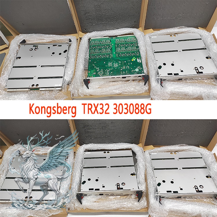

.jpg)
.jpg)
.jpg)


.jpg)