Many products have not yet been listed online; please contact us for more
information.
If the product model differs from the displayed image, the model number
takes precedence. Please contact us for specific product photos; we can arrange
for warehouse staff to take and verify them.
We operate 76 shared warehouses globally, so it may sometimes take a few
hours to provide you with an accurate response; we appreciate your
understanding. Rest assured, we will address your inquiries as quickly as
possible.
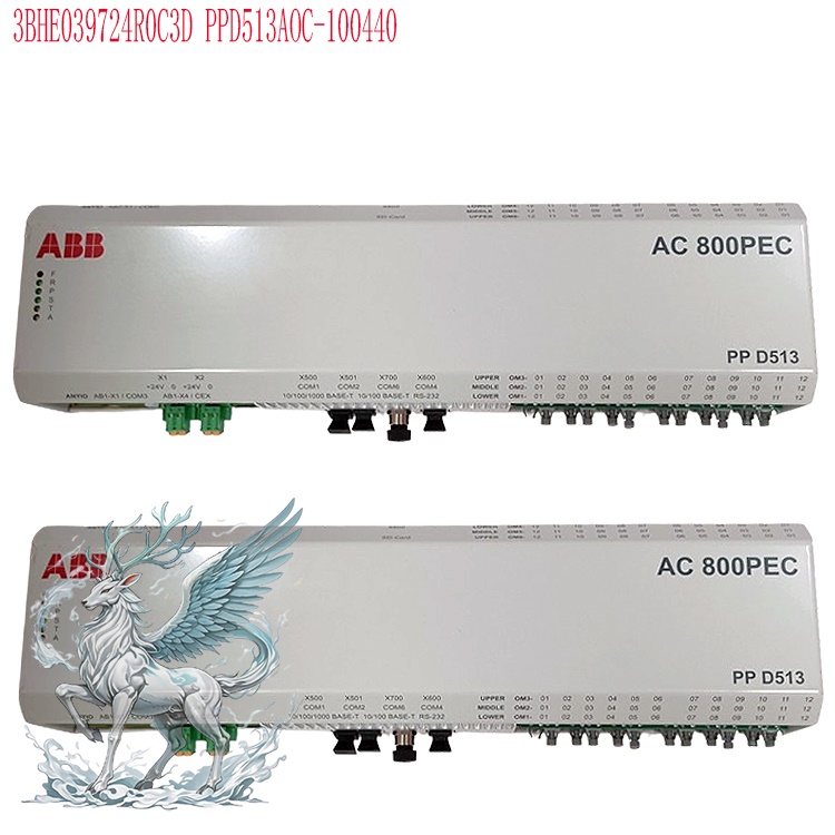
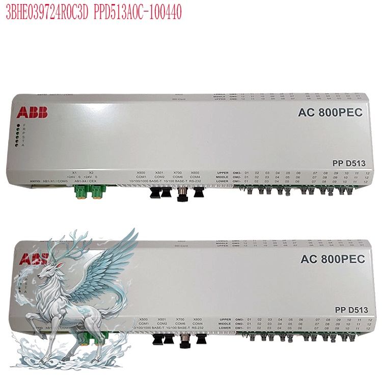
3BHE039724R0C3D Alternative Names:
AC800PEC System Controller 3BHE039724R0C3D
3BHE039724R0C3D Controller Drive Module
High-Performance Excitation Control Unit 3BHE039724R0C3D
The ABB 3BHE039724R0C3D excitation controller is a core excitation control unit based on ABB’s high-performance AC 800PEC control platform. It belongs to
the control-layer hardware of the ABB UNITROL excitation system series. It
primarily handles the computation, control, and protection functions for
synchronous motor excitation regulation, offering a control accuracy of ±0.5%
and high-speed dynamic response capabilities.
Operating Principle
This excitation controller operates based on a closed-loop negative
feedback control principle; the complete regulation process is as follows:
Signal Acquisition and Deviation Calculation: Real-time operating
parameters—such as terminal voltage, stator current, and rotor excitation
current of the synchronous generator or motor—are acquired via front-end
measurement circuits. After converting these physical quantities into standard
control signals, they are compared against internally preset reference values
(such as voltage setpoints and excitation current setpoints) to generate a
deviation signal. Control Algorithm Processing: It features a built-in,
configurable PID control algorithm supporting multiple modes, such as Automatic
Voltage Regulation (AVR) and Manual Field Current Regulation (FCR). Based on the
magnitude and trend of error signals—and incorporating auxiliary logic like
Power System Stabilizers (PSS), under/over-excitation limiters, and
Volts-per-Hertz limiters—it calculates the trigger control values for the
power rectification unit.
Excitation Power Output Control: The output trigger signals control the
firing angle of the downstream thyristor rectifier bridge (or IGCT power unit)
to adjust the magnitude of the rectified DC excitation current. Changes in
excitation current synchronously alter the magnetic field strength of the
synchronous motor rotor, thereby regulating the stator-side induced voltage and
reactive power output.
.jpg)
Closed-Loop Feedback Correction: Adjusted operating parameters are
recaptured by the acquisition circuit to continuously correct control errors,
establishing a complete closed-loop control system that stabilizes the
controlled variable within the set range.
Additionally, the controller integrates IGCT drive and snubber
technologies, offering low conduction losses and high blocking voltage
capabilities. It achieves a rapid response time of less than 20ms, meeting the
need for quick regulation during grid transient conditions.
Core Functions
Terminal Voltage Stabilization Control: This is the fundamental core
function of the excitation controller. Regardless of synchronous motor load
fluctuations or grid voltage disturbances, it maintains the terminal voltage
precisely at the set value by adjusting the excitation current in real-time,
ensuring the quality of the supply voltage.
.jpg)
Reactive Power and Power Factor Regulation: During grid-connected
operation, the unit's reactive power output is controlled by adjusting the
excitation current, enabling rational reactive power distribution among
parallel-connected units. It can also operate according to a set power factor to
optimize the unit's power quality and operational efficiency.
Power System Stability Enhancement: It supports Power System Stabilizer
(PSS) functionality to suppress low-frequency oscillations and improve the
grid's transient stability. In the event of a grid fault, it can provide rapid
voltage support through forced excitation, helping the system restore stable
operation.Equipment Protection and Fault Handling: Integrates multiple
protection logics—including monitoring for overcurrent, short-circuit,
overvoltage, undervoltage, loss of excitation, and rotating diode faults. Under
abnormal conditions, it rapidly executes limiting adjustments or triggers
field-suppression sequences to prevent damage to the synchronous motor rotor and
excitation power unit, thereby ensuring equipment safety.
Multi-mode Operation: Supports various operating modes such as automatic,
manual, and preset control. Seamless, bumpless switching between modes is
achievable, meeting operational requirements for unit startup, grid connection,
load operation, and maintenance.
Application Areas
Power Generation Industry: Serves as the core control component for
excitation systems in various synchronous generators. It is widely used in
thermal, hydroelectric, gas turbine, combined-cycle, and pumped-storage power
plants, accommodating generator units of diverse capacity ratings.
Large-scale Industrial Synchronous Drives: Used for the excitation control
of large synchronous motors in sectors such as metallurgy, mining, chemicals,
and building materials. It ensures smooth motor startup, variable-speed
operation, and power factor optimization, making it suitable for high-power
drive applications.
Power Grid Support Facilities: Supports synchronous condensers and dynamic
reactive power compensation devices within substations. Through excitation
regulation, it contributes to grid voltage support and reactive power
adjustment, enhancing overall grid operational stability.
Industrial Automation Power Electronics Systems: Integrated into
high-precision industrial power electronics control systems as an excitation
control unit, providing reliable excitation regulation capabilities for power
supply and drive equipment in industrial process control. ABB AC800PEC Series
Excitation Control Module: Closed-Loop Feedback Control Architecture
The ABB AC800PEC serves as the core control platform for the UNITROL series
excitation systems. Its closed-loop feedback control employs a layered, nested
architecture—comprising "hardware-layered physical links," "dual-loop nested
control logic," and "three-level real-time software scheduling"—capable of
spanning the entire time scale from nanosecond-level pulse response to
millisecond-level system regulation. It also supports dual-channel redundancy
and fault tolerance, representing a classic architecture for high-performance
synchronous motor excitation control.
I. Hardware Closed-Loop Physical Layer Architecture
In terms of the physical signal link, the complete closed-loop control
system is divided into four functional layers, forming a continuous signal flow
along the path of "acquisition → computation → output → feedback":
Front-end Signal Acquisition and Conditioning Layer: Centered on I/O modules such as the PEC80-CIO-FU (e.g., PC D235 A), this layer acts as the entry
point for closed-loop signals. It is responsible for acquiring analog
signals—such as synchronous motor terminal voltage, stator current, rotor
excitation current, and winding temperature—as well as digital status signals
from circuit breakers and limit switches. Equipped with built-in electrical
isolation, filtering circuits, and high-precision A/D converters, it converts
high-voltage field signals into standard digital signals suitable for controller
processing; the typical analog sampling period is 400 μs. This layer also
acquires feedback signals from the power stage, serving as the hardware medium
for closed-loop feedback.
Core Control and Computation Layer: Centered on main CPU modules such as
the 3BHE039724R0C3D and 3BHE046836R0101 GFD563A101 or 3BHE046836R0102 GFD563A102, this layer acts as the computational hub for
closed-loop regulation. It receives digital signals from the acquisition layer
and executes closed-loop regulation algorithms, limiting logic, and state
machine operations to generate control commands. It supports dual-module
hot-standby redundancy, where primary and backup units perform synchronous
acquisition and computation; in the event of a fault, a bumpless transfer
ensures the closed-loop control remains uninterrupted.
Pulse Output and Power Drive Layer: Implemented via FPGA hardware logic,
this constitutes the ultra-high-speed execution layer. This layer receives
firing angle commands from the control computation layer and generates
high-precision, highly synchronized firing pulses for thyristors or IGCTs to
directly drive the downstream power rectifier bridge. With a response speed in
the 25-nanosecond range and no software computation latency, this layer ensures
rapid and accurate excitation power output.
The feedback acquisition link consists of two stages: first, primary
feedback, where core controlled variables—such as excitation current and
generator terminal voltage—are transmitted from power-side sensors back to the
front-end acquisition layer to form the main closed-loop control; second,
pulse-level feedback, where the output and conduction states of the firing
pulses are fed directly back to the FPGA layer, enabling microsecond-level pulse
verification and rapid fault blocking to form a hardware-based
micro-closed-loop.
II. Core Control Loop: Nested Dual-Loop Logic
The core functions of excitation control are implemented via a nested
dual-loop structure comprising an outer voltage loop and an inner current loop.
These two loops are decoupled based on time scales and work collaboratively to
perform regulation tasks:
Outer Loop: Automatic Voltage Regulation (AVR, automatic mode)
Controlled Object: Terminal voltage of the synchronous generator or
motor
Setpoint Input: System-preset voltage reference value; allows for the
superposition of reactive power droop, PSS (Power System Stabilizer) auxiliary
control, and remote voltage regulation commands
Feedback Input: RMS values of the three-phase terminal voltage
transmitted from the acquisition layer
Regulation Algorithm: PID algorithm with filtering; control cycle ranges
from 1 ms to several milliseconds
Function: As the outer loop, it maintains terminal voltage stability and
responds to slow disturbances such as grid voltage fluctuations and load
changes; its output serves as the setpoint for the inner current loop. Inner
Loop: Excitation Current Regulation Loop (FCR, manual mode)
Controlled Variable: DC excitation current in the rotor circuit
Setpoint Input: Output command from the AVR outer loop (automatic mode) or
manually set current reference value (manual mode)
Feedback Input: Sampled current value from the DC side of the excitation
system
Regulation Algorithm: PI regulation algorithm; control cycle of 100–400
μs
Function: As the inner loop, it features a response speed significantly
faster than the outer loop. It is responsible for rapidly tracking the current
setpoint and suppressing fast disturbances—such as fluctuations in the
excitation power supply or changes in rectifier bridge characteristics—serving
as the direct control loop for excitation power output.
In addition to the two main loops, the architecture incorporates multiple
closed-loop protection and limiting functions, including over-excitation
limiting, under-excitation limiting, V/Hz limiting, and stator over-current
limiting. When operating parameters approach safety thresholds, the limiters
automatically take over the control loop to constrain the controlled variables
within permissible ranges, thereby achieving an integrated closed-loop system
for both protection and regulation.
III. Software Scheduling: Three-Level Real-Time Hierarchical
Architecture
The AC800PEC platform categorizes various closed-loop control tasks into
three software levels based on real-time requirements. Each level utilizes
specific development tools and execution cycles, striking a balance between
performance and flexibility:
Level 3: Ultra-high-speed hardware logic layer (nanosecond to microsecond
range)
Implementation: FPGA-based, developed using VHDL; implemented as fixed
firmware that cannot be modified by the user
Typical Cycle: 25 ns – 25 μs
Closed-loop Functions: Trigger pulse generation and modulation, pulse loss
detection, hardware-level rapid blocking for over-current and over-voltage
conditions, and high-speed I/O read/write operations. This layer constitutes a
hardware-level micro-closed-loop, enabling the fastest fault response and
precise pulse control. Level 2: Fast Control Algorithm Layer (Microsecond to
Millisecond Range)
Implementation: Based on MATLAB/Simulink modeling; C code is automatically
generated, downloaded, and executed.
Typical Cycle Time: 100 μs to 5 ms (the typical cycle for the main
excitation loop is 400 μs).
Closed-loop Functions: Executes core AVR and FCR dual-loop regulation
algorithms, PSS stability control, various limiter logic functions, and fault
detection and handling. This is the core software layer for closed-loop
excitation control, determining the system's regulation precision and dynamic
response speed.
Level 1: System Monitoring and Management Layer (Millisecond Range and
Above)
Implementation: Based on the IEC 61131-3 standard; programmed using the
Control Builder tool.
Typical Cycle Time: 10 ms and above.
Closed-loop Functions: Handles control mode switching, setpoint
distribution, parameter tuning, HMI interaction, communication with
DCS/upper-level systems, event logging, and fault recording. While this layer
does not directly participate in real-time regulation, it serves as the
top-level management unit for the closed-loop system, facilitating control
objective adjustments and system status monitoring.
IV. Redundant and Fault-Tolerant Closed-Loop Design
To ensure high reliability in industrial applications, the AC800PEC series
closed-loop architecture supports a comprehensive redundancy design:
Dual-Channel Redundant Closed-Loop: Supports primary and backup control
channels. Both channels independently acquire feedback signals and execute
closed-loop algorithms synchronously, with outputs selected via a voting
circuit. In the event of a single-channel failure, bumpless transfer occurs
within ≤200 ms, ensuring the closed-loop regulation process remains
uninterrupted.
Independent Feedback for Backup Channel: The backup channel continuously
participates in signal acquisition and closed-loop calculations, maintaining a
control output state synchronized with the primary channel. This ensures no
control jumps occur during switching, thereby guaranteeing stable unit
operation. 5. Complete Closed-Loop Workflow
Analog signals from the field undergo filtering and A/D conversion via the
I/O module before being sent to the high-speed control algorithm layer;
The algorithm layer compares the feedback signal with the setpoint to
calculate the error; after PID/PI processing and the integration of limiter and
PSS correction values, a firing angle command for the rectifier bridge is
generated;
The firing angle command is transmitted to the FPGA layer, which generates
high-precision firing pulses to drive the power rectifier bridge and adjust the
excitation current;
The resulting excitation current and generator terminal voltage are fed
back to the I/O acquisition layer via sensors, completing a main closed-loop
cycle; simultaneously, the pulse status is fed back to the FPGA to verify the
hardware-level micro-loop;
The system monitoring layer monitors the closed-loop operation in real
time, responds to external commands to modify control parameters or switch
operating modes, and logs operational data.
Recommended related products:
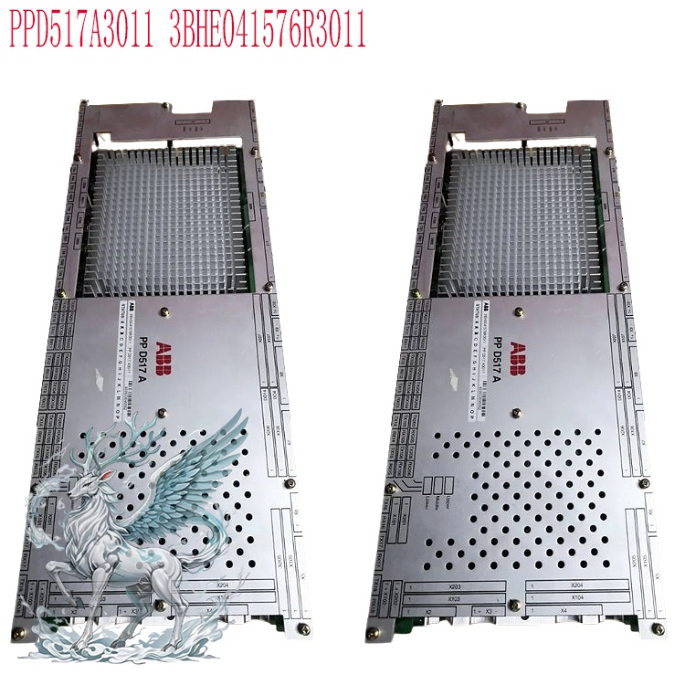
3BHE041576R3011 PPD517A3011
3BHE051476R3011 PPD517
3BHE041576R3011 PPD517
3BHE041576R3011 PPD517
PPD539A 3BHE039770R0102
PPD539A102 3BHE039770R0102
GFD212A 3BHE020357P201
3BHE020356R0101 GFD212
3BHE022294R0101 GFD233
3BHE022294R0103 GFD233
3BHE046836R0101 GFD563
3BHE046836R0102 GFD563A102
ABB 5SHY35L4503
3BHE031197R0001 GBU72
3BHE055094R0002 GBU72
L003748-AR ABB-3BSX108237R300
5SGY3545L0010 3BHB006485R0001
5SHY35L4503 3BHB004692R0002
More......


 ABB
ABB GE
GE HONEYWELL
 TRICONEX
 KONGSBERG
 EMERSON
 FOXBORO
 MOTOROLA
 VIBRO-METER
 ICS TRIPLEX
 WOODWARD
 BENTLY NEVADA
 OTHER
OTHER Home
Home.jpg)
.jpg)


.jpg)
.jpg)
.jpg)
.jpg)