All products on this site are
specialized items subject to fluctuating market prices.
Please rely on the quote provided by
customer service, as the listed prices are not final.
Before placing an order, please contact
customer service to confirm details such as the model, product specifications,
and pricing.
New units are available for sale; please
contact customer service for further discussion.
3BHE051476R3011
– Alternative Names:
Excitation
Control Unit 3BHE051476R3011
3BHE051476R3011
Converter Control Unit
PLCMO
Communication Redundancy Unit 3BHE051476R3011
I.
Operating Principle
The
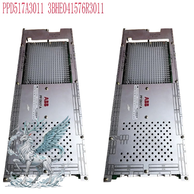
3BHE051476R3011 is an excitation central processing unit belonging to the
ABB AC800PEC platform.
It serves as the core control board for the synchronous generator excitation
system, acting as the system's computational and control hub.
The module acquires real-time analog signals (via PT/CT) such as generator
terminal voltage, stator current, excitation current,
and rotational speed. These signals undergo analog-to-digital conversion before
being processed using a dual-loop PID control architecture: an outer loop for
generator terminal voltage (AVR - Automatic Voltage Regulation) and an inner
loop for excitation current. Based on the deviation between the setpoint and
actual feedback, the unit calculates control pulses in real-time and outputs
drive commands to the excitation power unit. This regulates the excitation
output current and alters the rotor magnetic field strength of the synchronous
generator, thereby stabilizing the generator's terminal voltage and reactive
power.
The
unit incorporates control and protection algorithms—such as Power System
Stabilizer (PSS), Over-Excitation Limiter (OEL), Under-Excitation Limiter (UEL),
and Volts-per-Hertz (V/Hz) Limiter—to suppress low-frequency grid oscillations
and prevent abnormal operating conditions such as generator under-excited
operation (leading power factor), over-excitation, and excessive magnetic flux.
Supports switching between multiple modes—including automatic constant voltage,
constant power factor, constant reactive power, and manual constant excitation
current—and features built-in hardware self-diagnosis, event waveform capture,
and fault recording capabilities. It communicates via industrial bus with power
plant DCS and HMI monitoring systems to handle parameter downloading, status
uploading, and alarm transmission. It supports redundant configuration, enabling
rapid, bumpless switching to a backup controller in the event of a main
controller failure to ensure uninterrupted excitation system operation.
II.
Application Areas
Thermal
Power Generation: Excitation control for steam turbine generator units,
including large-scale thermal power plants and gas turbine combined-cycle power
plants.
Hydropower
Generation: Hydro-generator units, suitable for conventional hydropower and
pumped-storage units.
.jpg)
Nuclear
Power and Captive Power Plants: Auxiliary generator units for nuclear power
plants; captive synchronous generator units for large industrial enterprises in
sectors such as petrochemicals, steel, and cement.
Distributed
Energy and Emergency Power: Large diesel synchronous generator units and
island-mode power plants.
Large
Synchronous Motor Drive Applications: Excitation regulation for large
synchronous motors (e.g., compressors, ball mills) in metallurgy and chemical
industries.
III.
Core Functions
Voltage
Stability Control: Real-time regulation of generator rotor excitation current to
maintain stable terminal voltage. During grid-connected operation, it handles
reactive power regulation, supports grid voltage, responds rapidly to load
fluctuations and grid disturbances, and suppresses voltage deviations.
Unit
Grid Connection and Operating Condition Management: Coordinates with
synchronization devices to control generator grid connection; manages excitation
logic across the entire process—including startup/shutdown, load ramping
(increase/decrease), and disconnection—ensuring smooth switching of excitation
modes before and after grid connection.
Power
System Oscillation Damping: Features a built-in Power System Stabilizer (PSS)
function that uses supplementary control signals to suppress low-frequency power
oscillations between the generator and the grid, thereby enhancing the power
system's dynamic stability limits. Unit Protection and Operating Limit Control:
Integrates various excitation limiters to automatically constrain excitation
output under conditions such as under-excitation, over-excitation, and
Volts-per-Hertz (V/Hz) limit violations; protects the generator rotor, stator,
and excitation power circuits to prevent equipment damage; monitors the module's
own hardware, sampling, and communication for faults, triggering alarms or safe
switchovers as necessary.
System
Communication and Data Management: Acts as the interface between the excitation
system and the plant-wide monitoring system; uploads data such as voltage,
current, excitation status, and fault records; receives setpoint commands from
the supervisory system; and enables remote monitoring, parameter setting, and
event tracing.
.jpg)
Redundancy
for Continuous Operation: Supports a dual-redundant control architecture;
automatically switches to the backup unit in the event of a main processing unit
failure to prevent excitation system trips and shutdowns, thereby enhancing the
reliability of continuous power supply from the power plant.
IV.
Routine Maintenance Methods for the ABB 3BHE051476R3011
Excitation Central
Processing Unit
1.
Daily Inspections (Daily / Per Shift)
Status
Indicator and Panel Check: Observe the LED status lights on the front of the
module to confirm the "Run" light is normal and no alarm or fault lights are
illuminated; check the HMI or supervisory system to read module self-diagnostic
information and confirm the absence of hardware faults, communication anomalies,
or sampling limit violations; promptly record events and faults, analyze the
root cause of alarm information, and avoid clearing alarm records
arbitrarily.
Operating
Parameter Verification: Verify acquired values such as terminal voltage,
excitation current, reactive power, and rotational speed against field PT/CT
secondary measurements; observe AVR regulation stability to ensure there are no
frequent fluctuations or overshoot phenomena; confirm that the control mode
(Auto/Manual, Constant Voltage/Constant Reactive Power) matches the current
operating conditions.Environment and Cabinet Inspection: Check the temperature
and humidity of the excitation cabinet to ensure the internal temperature
remains within the module's permissible range and that there is no condensation
or dampness; verify the proper operation of internal air conditioners and
ventilation fans; ensure the cabinet is free from dust accumulation, odors,
vibration, and sources of strong electromagnetic interference; and confirm the
cabinet door seals are intact.
Communication
Link Inspection: Check the connection status of redundant fiber-optic cables and
communication network cables; verify normal data exchange between the host
computer/DCS and the excitation unit, ensuring no packet loss or interruptions;
for units with redundant configurations, check the synchronization status
between primary and standby modules and ensure there are no alarms regarding
abnormal primary-standby switching.
2.
Periodic Preventive Maintenance (Quarterly)
Visual
and Wiring Inspection: After powering down, inspect module boards for corrosion,
bulging, or burn marks; check terminal blocks, fiber-optic connectors, and
shielded cable connectors for looseness, oxidation, or rust; tighten signal
terminals to specified torque values; verify reliable grounding of shielding
layers and ensure high-voltage and low-voltage cables are routed separately to
prevent interference.
Dust
Removal and Cleaning: Use dry, clean, low-pressure compressed air to blow dust
off module heat dissipation channels and board surfaces (do not direct
high-pressure airflow at chips or connectors); do not wipe circuit boards
directly with liquid cleaners; clean fiber-optic end faces to ensure stable
optical signal transmission.
Redundancy
Switching Test (under permissible unit operating conditions): For dual-redundant
systems, conduct bumpless transfer tests between primary and standby controllers
according to procedures; verify that the primary-standby switching function
operates correctly during faults and that the switching process causes no
excitation disturbances or unit fluctuations.
Sampling
Circuit Calibration: Verify and calibrate voltage and current analog sampling
circuits to ensure sampling accuracy and eliminate zero-point drift; check
parameter statuses for OEL, UEL, V/Hz, and PSS-related limiting
logic.
3. Annual Maintenance (Unit Outage/Overhaul
Window)
Comprehensive
Parameter Backup: Use commissioning software to fully export excitation control
parameters, limiting parameters, PSS parameters, and event recording files;
maintain dual backups (local and off-site). Original configurations must be
backed up before any parameter modifications.
Comprehensive
Hardware Inspection: Inspect board capacitors and internal backup batteries. The
module contains an onboard lithium battery; replace it approximately every three
years or upon receiving a low-battery alarm to prevent the loss of clock
settings and event records during power outages. Check power input circuit
ripple and supply voltage stability.
Static
Control Function Testing: With the unit shut down, apply simulated PT/CT signals
to test AVR closed-loop regulation, various limiting and protection logic, PSS
supplementary control, and mode switching functions; verify regulation accuracy
and protection setpoints.
Firmware
Assessment and Upgrade: Evaluate the official ABB firmware version. If a version
with known defects is identified, perform a full parameter backup and execute
the firmware upgrade during the scheduled outage window; re-verify all control
parameters after the upgrade.
Integrated
Functional Commissioning: Conduct joint commissioning of the excitation unit
with the power unit, synchronization device, and DCS system to verify command
issuance, status feedback, and trip signal interaction logic.
4.
Corrective Maintenance (Post-Fault Maintenance)
In
the event of module alarms, regulation anomalies, or communication
interruptions, prioritize retrieving internal fault records and event logs to
distinguish between external signal interference, primary equipment issues, and
CPU board malfunctions.
For
minor, sporadic alarms, power down the unit, let it sit for 30 seconds, then
power it back up to reset and observe if the alarm recurs; do not force the unit
into operation if alarms persist.
In
cases of hardware damage, replace the board with an identical model; download
backed-up parameters after replacement and ensure static tests pass before
putting the unit back into service.
5.
Long-term Maintenance Considerations
Spare
Parts Management: Stock spare modules of the same model; store them in a
temperature-controlled, dry environment using anti-static packaging. Anti-static
measures: An anti-static wrist strap must be worn when handling circuit boards;
touching chips or gold fingers with bare hands is prohibited.
Documentation
management: Establish and maintain logs to record inspections, parameter
modifications, firmware upgrades, battery replacements, and fault resolution
details.
Prohibited
actions: Modifying core control parameters while the unit is running is
prohibited; bypassing protection or limiting logic without authorization is
prohibited.
Recommended
related products:
PPD539A
3BHE039770R0102
PPD539A102
3BHE039770R0102
GFD212A
3BHE020357P201
3BHE020356R0101
GFD212
3BHE022294R0101
GFD233
3BHE022294R0103
GFD233
3BHE046836R0101
GFD563
3BHE046836R0102
GFD563A102
ABB
5SHY35L4503
3BHE031197R0001
GBU72
3BHE055094R0002
GBU72
L003748-AR
ABB-3BSX108237R300
5SGY3545L0010
3BHB006485R0001
5SHY35L4503
3BHB004692R0002
More......


 ABB
ABB GE
GE HONEYWELL
 TRICONEX
 KONGSBERG
 EMERSON
 FOXBORO
 MOTOROLA
 VIBRO-METER
 ICS TRIPLEX
 WOODWARD
 BENTLY NEVADA
 OTHER
OTHER Home
Home
.jpg)
.jpg)


.jpg)
.jpg)
.jpg)