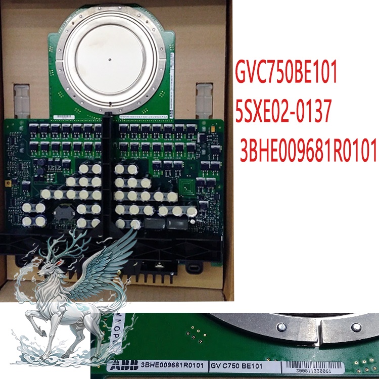
Many products are not yet listed. Please contact us for more
information.
If the product model differs from the displayed image, the model number
shall prevail. Please contact us for specific product images; we will arrange to
take photos in our warehouse for confirmation.
We have 76 shared warehouses worldwide, so it may sometimes take several
hours to accurately return the information to you. We apologize for any
inconvenience. Of course, we will respond to your inquiries as soon as
possible.
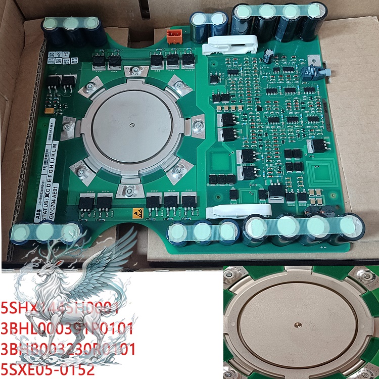
5SHX1445H0001 Other Names:
High-Power Integrated Gate Commutated Thyristor (IGCT) Semiconductor Module
5SHX1445H0001
5SHX1445H0001 High-Voltage Inverter Module
I. Working Principle
IGCT combines the advantages of both
.jpg)
and transistors:
Conduction Phase: Exhibits thyristor characteristics, low on-state voltage
drop, low conduction loss, and high current carrying capacity;
Turn-off Phase: Rapid gate commutation forces the main device current to
the gate circuit, achieving rapid turn-off, unlike traditional GTOs;
This model integrates a drive circuit, greatly reducing system circuit
inductance, simplifying inverter hardware design, and improving reliability.
II. High-Power High-Speed Power Switch
As a high-speed switching device in the main circuit, it withstands high
voltage and high current, and is controlled to complete conduction and turn-off.
When on, it carries a large current in the main circuit; upon receiving a gate
turn-off signal, it can quickly and forcibly turn off the main current, unlike
ordinary thyristors which cannot self-turn off.
AC-DC Power Conversion (Inverter/Rectifier)
Inverter: Converts DC bus power into AC power with adjustable amplitude and
frequency to drive medium-voltage high-power motors. It is a core component of
the power unit in medium-voltage frequency converters such as ACS6000 and
ACS1000.
.jpg)
Rectifier: Can also be used to convert AC to DC, achieving bidirectional
energy conversion and adapting to four-quadrant drive conditions.
III. Short-Circuit Fault Tolerance
The press-fit encapsulation structure provides short-time short-circuit
current tolerance. When a short-time short-circuit fault occurs, it can
withstand the fault impact, providing time for system protection to operate and
improving equipment reliability.
Speed Regulation and Reactive Power Regulation in System Integration
In frequency conversion drive systems: Through high-frequency on/off
control, motor speed and torque regulation are achieved, used in fans, pumps,
rolling mills, and mining drives. In SVG/excitation devices: Participates in
reactive power compensation and generator excitation regulation, completing grid
reactive power and voltage control.
IV. Integrated Gate Drive Interface, Simplifying Overall Design
The module has a built-in IGCT gate interface, which, in conjunction with
the matching drive board, completes device triggering, shutdown, and device
status feedback, reducing external buffer circuits and lowering the overall
hardware complexity.
V. Role in Complete Equipment Sets
Within ABB medium-voltage frequency converters, excitation, and static
compensation devices, multiple of these modules combine to form a power unit,
which is the hardware execution unit for power conversion. The control system
issues commands, and this module actually completes the power conversion and
output.
VI. Typical Application Scenarios
1. Industrial Medium and High Voltage Variable Frequency Drives (Main
Application Area)
Compatible with ABB ACS1000 and ACS6000 series medium-voltage frequency
converters.
1. Mining: Main hoists, belt conveyors, and large crusher drives;
.jpg)
Metallurgy & Steel Rolling: Rolling mill main drives, fans, pumps, and
compressors;
Cement & Building Materials: Large kiln fans and high-power air
compressors;
Water & Chemical Industry: Large high-pressure water pumps and process
compressor speed control.
2. Power Generation & Power Grid Sector
Excitation systems for generators in thermal and hydropower plants, serving
as excitation power unit switching devices;
Static Var Generators (SVG) and Static Var Compensators (SVC), used for
power grid reactive power regulation and voltage stabilization;
High-power converters for plant power supply.
3. New Energy Industry
Large wind turbine generator converters, enabling wind turbine power
conversion and grid connection;
Large centralized photovoltaic inverters.
4. Shipbuilding & Marine Engineering
Marine electric propulsion frequency converters, used in propulsion systems
for large merchant ships, LNG carriers, and offshore platforms;
High-power power supply and frequency conversion drive equipment for
offshore platforms.
5. Rail Transit Traction
Traffic traction converter for locomotives, used for traction motor speed
regulation and regenerative braking energy feedback.
6. Other High-Power Special Equipment
High-power test power supplies, medium-frequency power supplies, large
industrial UPS, energy storage converters (PCS).
VII. Precautions for Use
1. Mechanical Installation (Crimping and Encapsulation Focus)
The clamping force must strictly comply with the manual requirements.
Insufficient pressure: increased contact resistance, severe overheating, and
easy overheating and burnout; excessive pressure: internal chip cracking, direct
damage to the device. Do not press-fit by feel; torque or pressure fixtures must
be used.
The contact surfaces of the device must be flat, clean, and free of burrs,
scratches, dust, and metal debris; the heat dissipation contact surfaces should
not be coated with excessively thick thermal grease; a thin, even layer is
sufficient.
The device has double-sided heat dissipation; both heat sinks must ensure
good contact; avoid impacts to the ceramic insulating shell during installation,
as ceramic cracking will directly cause high-voltage breakdown.
1. Disassembly and Assembly: The module must not be dropped or struck
during disassembly and assembly. The internal chips are extremely fragile; even
if the exterior appears intact, there may be hidden internal damage.
2. Electrical Wiring and Driver Matching: Only original
manufacturer-matched gate driver boards must be used. Do not use other IGCT
drivers. Incompatible drive voltages and shutdown pulse timings will result in
failure to shut down or device failure.
Gate cable length and diameter must strictly adhere to the drawings. Gate
circuit wiring should be as short as possible to reduce circuit inductance.
Loose or poorly connected gate terminals are strictly prohibited.
Main circuit high-voltage wiring must be securely tightened to prevent
overheating and arcing under high current. Ensure proper high-voltage insulation
between the main circuit and gate circuit.
This IGCT is sensitive to du/dt and di/dt. The system buffer absorption
circuit must not be arbitrarily removed or have its parameters altered.
3. Cooling and Operating Environment: Supports water cooling/forced air
cooling. The temperature and flow rate of the cooling medium must be within
specifications. For water-cooled models, prevent leaks and condensation, as
condensation can cause high-voltage creepage and breakdown.
Operating temperature control: -40℃ to +125℃. Chip junction temperature
must not exceed 125℃; prolonged operation above this temperature will accelerate
chip aging and shorten its lifespan.
Avoid frequent, large-scale load impacts during equipment operation.
Frequent short-circuit impacts will accelerate device aging.
4. Debugging, Repair, and Spare Parts
Before powering on: Check clamping force, gate wiring, and insulation
resistance. Only proceed with low-voltage testing after confirming everything is
correct. Do not directly apply full high voltage. Prioritize low-voltage trigger
and shutdown tests.
If a module experiences a breakdown short circuit, do not replace only the
IGCT: Check the driver board, buffer capacitor, and freewheeling diode for
damage; otherwise, the new module will burn out again.
Spare parts are existing older components. Before installation, it is
recommended to perform withstand voltage and gate characteristic tests.
Prioritize replacing the entire assembly (IGCT + driver module); individual
component replacement is not recommended.
Storage environment: Dry, dust-free, and avoid moisture. For long-term
storage, moisture-proof treatment is recommended; outdoor storage is
prohibited.
5. Safe Operation
After power-off maintenance, be sure to fully discharge the DC bus
capacitors. Residual high voltage can cause personal injury and damage to
components.
When the module is carrying high voltage, do not touch the terminals. Take
proper safety precautions during high-voltage testing.
Recommended related products:
5SHY3545L0014 3BHE019719R0101
5SHX1445H0002 3BHL000387P0101
5SHX14H4502 3BHB003230R0101
5SHX1960L0004 3BHL000390P0104
5SHX1960L0006 3BHB016120R0002
5SHX2645L0002 3BHB012961R0001
5SHX2645L0004 3BHL000389P0104
5SHX2645L0002 3BHE009681R0101
5SHY4045L0006 3BHE039203R0101
5SHY4045L0006 3BHE039203R0101
3BHB009885R0063 S-093M
3BHB009885R0005 S-093H
3BHB009885R5311 S-093R
3BHB012897R0003 S-053M
3BHB009885R0004 S-093H
3BHB009884R0021 S-073N
3BHB018008R0003 S-113H
S-093N 3BHB009885R0001
S-093N 3BHB009885R0021
3BHT300026R1 DI651
More......


 ABB
ABB GE
GE HONEYWELL
 TRICONEX
 KONGSBERG
 EMERSON
 FOXBORO
 MOTOROLA
 VIBRO-METER
 ICS TRIPLEX
 WOODWARD
 BENTLY NEVADA
 OTHER
OTHER Home
Home.jpg)
.jpg)
.jpg)


.jpg)
.jpg)