Many products are not yet listed. Please
contact us for more information.
If the product model differs from the
displayed image, the model number shall prevail. Please contact us for specific
product images, and we will arrange to take photos in our warehouse for
confirmation.
We have 76 shared warehouses worldwide,
so it may sometimes take several hours to accurately return the information to
you. We appreciate your understanding. Of course, we will respond to your
inquiries as soon as possible.
Other names for
3BHE019719R0101:
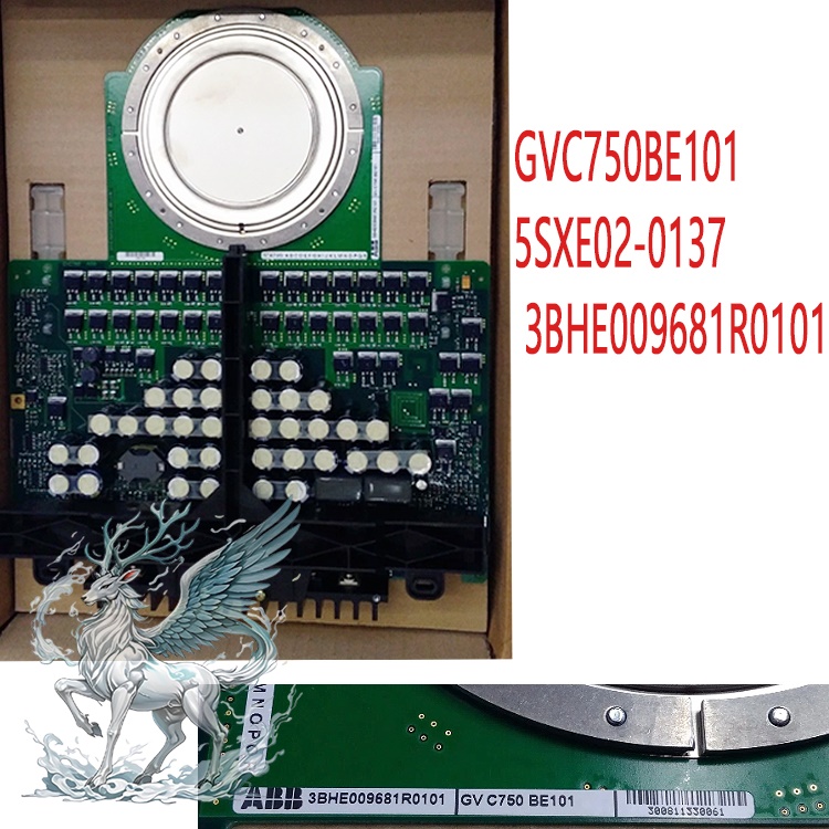
Reverse-conducting IGCT 3BHE019719R0101
3BHE019719R0101
Integrated Gate Commutated Thyristor, RC-IGCT
High-power Integrated
Gate Commutated Thyristor (IGCT) RC Semiconductor Module 3BHE019719R0101
I.
Basic Product Definition
This
device is a reverse-conducting RC-IGCT integrated gate commutated thyristor
power unit,
not simply a control board. It is the core power switching hardware of the ABB
UNITROL high-power excitation system and MEGADRIVE-LCI static frequency
converter excitation cabinet. It integrates an IGCT chip + gate driver board,
buffer absorption circuit, and water-cooling interface, directly undertaking
high-power AC/DC conversion for excitation, commonly known as an excitation
power module.
II.
Core Electrical Parameters (Water-cooled Standard for Excitation
Operation)
Blocking
Voltage VDRM: 6000V DC (Compatible with high-voltage excitation
rectifier/inverter topology)
Rated
Continuous Effective Current IT: 1960A (25℃ water-cooled)
Surge
Peak Current ITSM: 6000A (Short-time fault tolerance)
Switching
Frequency: Maximum 10kHz, excitation system normal operation 1~3kHz
Cooling
Method: Forced water cooling (module has built-in water interface, cannot be
air-cooled for long-term full load)
Operating
Environment: Operating 0~70℃, storage -55~100℃, humidity 5%~95%
non-condensing
Overall
Weight: Approximately 2.6kg, press-fit package, bolt-clamped heat sink
mounting
III.
Core Functions of the Excitation System (Exciter Scenario)
Excitation
Power Rectifier/Inverter Core Switch: In large steam turbine/hydro turbine
generator UNITROL 6000 In a high-power static excitation cabinet, it acts as a
three-phase controllable rectifier bridge power element, converting AC power
into adjustable DC excitation current to supply the generator rotor; in the
brushless exciter's frequency conversion excitation circuit, it functions as an
inverter unit, regulating the output power of the auxiliary exciter.
Built-in
integrated gate drive (precise excitation voltage regulation): It features a
built-in fiber optic trigger drive circuit that receives fiber optic pulse
signals from the AVR voltage regulator, rapidly switching on and off to control
the excitation output current. This, combined with the PSS power stabilizer,
enables rapid regulation of the generator terminal voltage and reactive
power.
Integrated
hardware protection (excitation fault protection): The module integrates
hardware protection circuits: gate undervoltage lockout, IGCT overcurrent and
short-circuit protection, over-temperature monitoring, and RC buffer absorption.
In the event of a rotor short circuit or excitation overcurrent on the
excitation side, the pulse is blocked at the microsecond level to prevent
excitation winding burnout and power device failure.
Low-loss,
high-power capacity: The IGCT combines the current-resistance of a thyristor and
the fast turn-off of an IGBT, resulting in low conduction losses under full
excitation conditions for large-capacity units. It is suitable for continuous
excitation operation of megawatt-level synchronous generators.
Integrated
structure:
The
module consists of two parts: a bottom water-cooled heat dissipation and
press-fit power chip + an upper gate drive control circuit board. It
incorporates an RC absorption capacitor, fiber optic trigger receiver circuit,
and status detection loop. Fiber optic isolation triggering ensures complete
isolation between strong and weak currents, resisting strong electromagnetic
interference from the excitation cabinet.
.jpg)
Excitation
system working logic: The AVR excitation regulator sends fiber optic pulse
signals → the module driver board receives the optical signals → controls the
IGCT to conduct/turn off at high frequency, completing three-phase AC
rectification and outputting an adjustable DC excitation current to supply the
generator rotor. The entire process of grid connection, reactive power
adjustment, forced excitation, and de-excitation relies on this module to
quickly adjust the conduction angle, achieving a response speed more than 10
times faster than ordinary thyristors, and exhibiting excellent dynamic
performance under forced excitation.
IV.
Typical Excitation Application Scenarios
ABB UNITROL 6000 High-Power
Static Excitation System (Megawatt-class
Thermal and Hydropower Units)
MEGADRIVE-LCI
Brushless Excitation Variable Frequency Drive (Auxiliary Exciter Control for Gas
Turbines and Pumped Storage Units)
Synchronous
Condenser High-Voltage Excitation Converter, Large-Capacity Static Var
Compensation (SVG) Excitation Power Cabinet
Large
Generator Set Excitation Cabinet: Power rectifier cabinet for 200MW/300MW/600MW
steam turbine generators and large-capacity hydro turbine generator self-excited
static excitation systems, with multiple modules connected in series/parallel
for expansion, adaptable to megawatt-level excitation power output.
ABB
Complete Equipment Sets: Standard power units for ABB EXC9000, UNITROL series
excitation systems, and ACS6000 medium-voltage variable frequency SFC static
variable frequency start-up excitation devices.
Other
extensions: High-voltage frequency converter, SVG reactive power compensation,
HVDC converter valve (universal for the same series).
V.
Common Faults and Troubleshooting
1.
Typical Damage Phenomena
Excitation
system reports power unit fault, fiber optic communication loss, excitation
overcurrent trip
Module
water cooling leak, driver board capacitor bulging, fiber optic receiver light
constantly off/always on
Insulation
test during shutdown: IGCT anode and cathode breakdown short circuit, gate open
circuit
2.
Rapid Damage Assessment
Power
off and drain the cooling system, measure the anode and cathode resistance of
the module main terminals: continuity/short circuit = chip breakdown and
scrap
No
voltage at 24V DC power supply to the fiber optic driver board: drive circuit
damage
Cooling
water circuit blockage, outlet water temperature exceeding 45℃: long-term
overheating accelerates component aging
High
current and high density: 1960A current per module, reducing parallel branches
in the power cabinet, reducing the excitation cabinet footprint;
Reverse
conduction RC Integrated: Built-in freewheeling diode eliminates the need for
additional parallel freewheeling devices in the excitation rectification,
simplifying the power circuit;
Fiber
optic isolated drive: Completely eliminates interference from the strong
magnetic field and rectifier harmonics in the excitation cabinet, preventing
excitation instability caused by pulse loss;
.jpg)
Low
conduction loss: Lower heat generation under high power conditions; water-cooled
continuous operation with controllable temperature rise;
Built-in
fault self-diagnosis: The driver board collects chip temperature, gate voltage,
and short-circuit status in real time, uploading module fault alarms to the
upper-level AVR.
VI.
Common Excitation Field Fault Judgment and Handling
1.
Typical Fault Phenomena
Generator
terminal voltage fluctuations, significant excitation current drift, reactive
power regulation failure;
Excitation
system reports "Power unit fault" or "Gate drive abnormality";
Excitation
failure, inability to reset after forced excitation, frequent blown fast fuses
in the power cabinet.
2.
Troubleshooting Steps
Visual
Inspection: Check for leaks in the water-cooling connector, bulging capacitors
on the driver board, and contaminated or broken fiber optic connectors.
Water-Cooling
Circuit Testing: Excessive flow rate and inlet/outlet water temperature
difference can cause the module's overheat protection to lock out.
Fiber
Optic Signal Testing: Replace the fiber optic transceiver channel to
differentiate between a damaged AVR transmitter board and a damaged IGCT driver
board.
Chip
Continuity Measurement: After powering off, use a multimeter to check for a
short circuit between the anode and cathode to determine if the IGCT chip is
short-circuited.
Driver
Board Power Supply Testing: A lack of auxiliary 24V power supply to the module
will prevent triggering.
.jpg)
3.
Damage Judgment Criteria
Chip
Breakdown (Anode-Cathode Straight Through), Large-Area Capacitor Burnout on the
Driver Board, Corrosion and Leakage of the Water-Cooling Base: Replace the
entire module.
Fiber
Optic Connector Damage Only, External Fuse Damage: Replace the auxiliary
component separately and reuse the power unit.
VII.
Installation and Maintenance Points
Mandatory
Heat Dissipation Requirements: A pure water cooling system is mandatory; air
cooling is prohibited. Cooling water conductivity and flow rate must strictly
comply with ABB exciter cabinet specifications.
Installation
Process: Crimping and sealing must be tightened to standard torque; uneven force
will cause localized overheating and burnout of the chip.
Wiring
Protection: Fiber optic loops should be kept away from exciter transformers,
busbars, and other areas with strong magnetic fields.
Recommended
related products:
5SHX1960L0006
3BHB016120R0002
5SHX1960L0006
3BHB016120R0002
5SHX2645L0002
3BHE009681R0101
5SHX2645L0004
3BHL000389P0104
5SHX2645L0002
3BHE009681R0101
5SHX2645L0004
3BHB003154R0101
5SHY3545L0003
3BHB004692R001
5SHY3545L0005
3BHB004692R0001
5SHY3545L0009
3BHB013085R0001
5SHY3545L0010
3BHE009681R0101
3BHB009885R0005
S-093H
3BHB009885R5311
S-093R
3BHB012897R0003
S-053M
3BHB009885R0004
S-093H
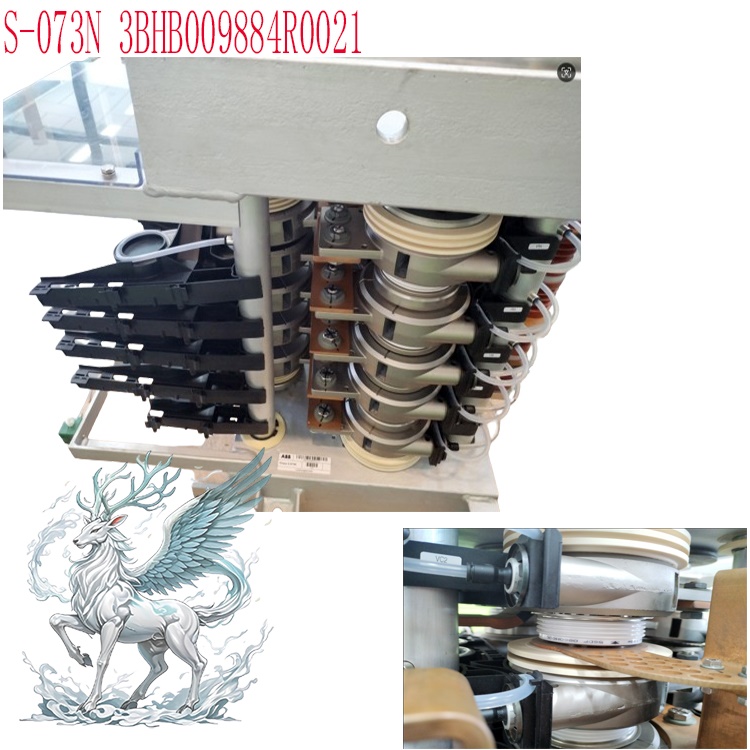
3BHB009884R0021
S-073N
3BHB018008R0003
S-113H
S-093N
3BHB009885R0021
More......


 ABB
ABB GE
GE HONEYWELL
 TRICONEX
 KONGSBERG
 EMERSON
 FOXBORO
 MOTOROLA
 VIBRO-METER
 ICS TRIPLEX
 WOODWARD
 BENTLY NEVADA
 OTHER
OTHER Home
Home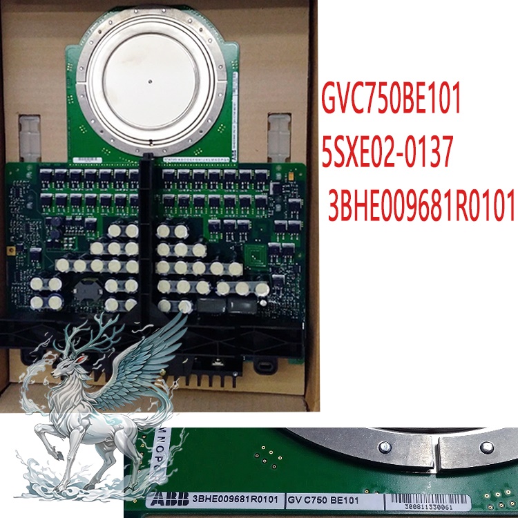
.jpg)
.jpg)
.jpg)