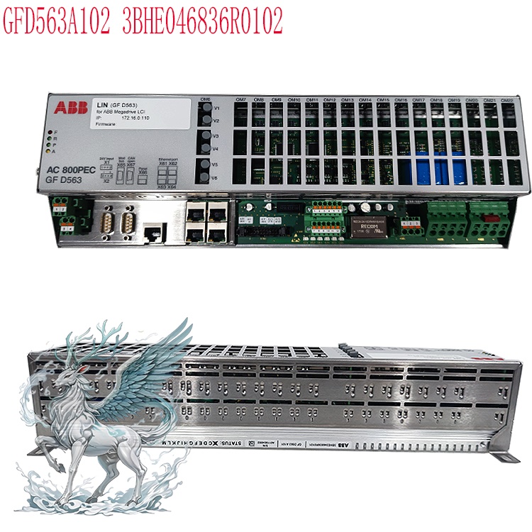
Many products have not yet been listed
online; please contact us for more options.
If there is a discrepancy between the
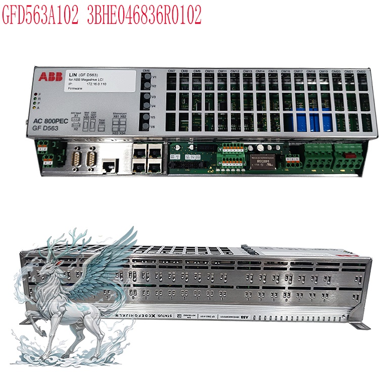
product model and the displayed image, the model number takes precedence. Please
contact us for specific product photos, and we will arrange for them to be taken
at the warehouse for verification.
We operate 76 shared warehouses
worldwide, so it may sometimes take a few hours to provide you with an accurate
response; we appreciate your understanding. Rest assured, we will address your
inquiries as quickly as possible.
3BHE020357P201
Alternative Names:
Controller Unit
3BHE020357P201
3BHE020357P201
UNITROL 6000 X-power Excitation
System
Excitation
Process Control Unit 3BHE020357P201
3BHE020357P201
Central Excitation Processor
I.
Operating Principle
The module utilizes
a core DSP processor and operates based on the principle of closed-loop negative
feedback regulation. The complete process is as follows:
Signal
Acquisition: Real-time acquisition of analog signals—such as generator terminal
voltage, stator current, excitation current, and grid voltage—followed by signal
conditioning and A/D sampling;
Calculation
and Comparison: Calculating the deviation between measured values (voltage/power
factor) and setpoints, and determining the required excitation output using PID
or specialized excitation control algorithms;
Pulse
Output: Outputting thyristor drive pulses to the excitation power cabinet
(thyristor rectifier bridge) to regulate the DC excitation current in the
excitation winding;
Closed-loop
Feedback: Change in generator magnetic field → change in terminal voltage →
re-sampling; continuous closed-loop operation maintains voltage stability;
Protection
and Diagnostics: Synchronous acquisition of various fault signals; if limits are
exceeded, trigger pulses are blocked, and alarm or trip signals are issued;
Communication
and Interaction: Uploading unit parameters, alarms, and waveform recording data
to the DCS or supervisory SCADA system, and
receiving remote control commands (e.g., increase/decrease excitation, switch
regulation modes).
.jpg)
Summary:
Acquires generator electrical quantities → processes data via excitation
algorithms → outputs trigger pulses to control the excitation power unit →
maintains stable terminal voltage/power factor.
II. Key Functions
Multi-mode
Excitation Regulation
Constant
generator terminal voltage regulation (AVR, most commonly used);
Constant
excitation current regulation (manual mode);
Constant
power factor / constant reactive power regulation;
Supports
bumpless transfer between automatic and manual modes to prevent voltage
disturbances during switching.
Generator
and Excitation System Protection: Includes over-excitation limiting,
under-excitation limiting, V/Hz limiting, over-current and over-temperature
protection, loss-of-excitation monitoring, and pulse fault self-diagnosis;
prevents damage to the unit caused by leading power factor operation or
over-excitation.
Self-diagnosis
and Fault Recording: Includes power-on self-test (POST) and real-time
hardware/channel self-monitoring; records events and waveforms upon fault
occurrence; front-panel LEDs indicate operation, fault, and communication status
to facilitate maintenance.
Communication
Functions: Supports Ethernet and serial interfaces for interaction with DCS,
HMI, and supervisory control systems;
supports data transmission, remote excitation adjustment (increase/decrease),
and remote activation/deactivation control.
Redundancy
Support: The Unitrol excitation system can be configured with dual
3BHE020357P201 redundant controllers; allows bumpless transfer to the standby
controller in the event of a master controller failure—ideal for critical power
plant units.
.jpg)
Logic
Control: Built-in excitation system sequential logic, including field flashing,
de-excitation, tracking, interlocking, and binary signal interlocking.
III.
Precautions for Installation, Commissioning, and O&M
Hardware
Installation
Strictly
Prohibit Hot-Swapping: Do not insert or remove this module while the rack
backplane is energized; doing so risks burning out the backplane gold fingers,
FPGA, or DSP chips. The module must only be installed or removed after the
cabinet's control power has been disconnected. This board is highly sensitive to
voltage dips during power-up. Backplane and Gold Fingers: Before installation,
inspect the backplane slots and module gold fingers to ensure they are free of
oxidation and oil stains; clean them regularly given the humid and dusty
environments typical of power plants; for cabinets subject to high vibration,
ensure module locking clips are securely fastened to prevent poor contact.
Power
Supply Requirements: The auxiliary power supply is 24V DC; excessive ripple must
be avoided. A UPS power supply is recommended to prevent voltage dips and
surges. Voltage dips during power-up can cause module initialization failures
and trigger "ERR" flashing faults (three flashes).
Electromagnetic
Environment: Keep the unit away from strong magnetic fields (such as excitation
power cabinets) and power cables. Analog signal lines and pulse drive lines must
be shielded and grounded at a single point. Route high-voltage and low-voltage
wiring separately to prevent interference that could cause voltage jitter or
false pulse triggering.
Environmental
Conditions: Operating temperature is generally -20°C to +60°C; ensure adequate
ventilation space within the cabinet to prevent overheating. Protect against
condensation, dust, and corrosive gases; the unit has an IP20 protection rating
and is intended for use only inside control cabinets.
Commissioning
and Parameters
Backup
Before Parameter Download: Before modifying excitation parameters, always back
up the complete parameter set and firmware version. When replacing a spare part
of the same model, ensure firmware versions match; mismatched versions can lead
to regulation anomalies or redundancy switchover failures.
Signal
Loop Verification: Verify PT/CT wiring polarity before commissioning; reversed
polarity can cause incorrect excitation system regulation and generator
overvoltage.
Static
Testing First: Conduct static simulation tests first—without connecting the
power units—to verify that regulation logic and limit/protection functions
operate correctly; proceed to dynamic testing with the power cabinet connected
only after successful static testing.
Redundancy
System: For the primary and standby 3BHE020357P201 units, synchronize
parameters and verify tracking functions to ensure bumpless transfer during
switchover.
Operation
and Maintenance
Routine
Inspections: Observe the status of panel LEDs; record module temperature, power
supply voltage, and communication status; regularly review event alarms. Spare
Part Replacement: Orders must specify the complete part number
(3BHE020357P201); units with the same model number but different firmware
suffix versions are not directly interchangeable.
Electrostatic
Protection: Wear an anti-static wrist strap when handling the module; static
electricity can directly damage DSP and FPGA chips.
Troubleshooting:
If the ERR indicator flashes, prioritize checking the quality of the 24V power
supply, backplane contact, and grounding; do not repeatedly cycle the power
blindly.
Safety
Criticals: The excitation system directly impacts generator safety. Parameter
modifications, online switching, and troubleshooting must adhere to the power
plant's work permit system to prevent incidents such as loss of voltage,
over-excitation, or underexcited operation (leading-power-factor operation).
IV.
Key Points on Common Faults
ERR
indicator flashes in a 3-cycle pattern: FPGA/DSP initialization timeout; likely
causes include poor backplane contact, a 24V voltage dip during power-up, or
excessive power supply ripple.
Regulation
drift or voltage fluctuation: PT/CT interference, poor shield grounding, or
loose analog terminals.
Redundancy
switchover failure: Mismatched firmware versions between primary and standby
units, unsynchronized parameters, or backplane communication channel faults.
V.
3BHE020357P201 Application Scenarios
1.
Power Generation (Primary Application)
Thermal
power plants (pulverized coal boilers, gas turbine combined-cycle units) and
excitation control cabinets for small-to-medium steam turbine generators;
suitable for new unit installations and retrofitting/replacing legacy excitation
systems. Typically paired with a redundant 3BHE020357P201 unit to enable
bumpless transfer upon primary controller failure, ensuring grid-side voltage
stability and compliance with grid codes.Hydropower Plants: Excitation control
for hydro-turbine generator units; handles significant load fluctuations (due to
changes in water head and flow) requiring rapid excitation response; supports
constant voltage/reactive power regulation, V/Hz control, and
under-excitation/over-excitation limiting.
Captive
Power Plants (Industrial Power Stations): Captive stations for chemical, steel,
paper, and cement enterprises (steam/gas turbine generator units); supports
dual-mode operation (islanded mode for in-plant power vs. grid-connected mode).
Islanded operation demands extremely high voltage stability; the module supports
islanded grid regulation logic.
Diesel/Gas
Internal Combustion Generator Units: Large and medium-sized gas and diesel
synchronous generator units (distributed energy, emergency backup stations);
serves as the excitation controller for grid-connected or backup power sources;
coordinates reactive power distribution during multi-unit paralleling.
2.
Oil & Gas and Marine Engineering (Ships/Offshore Platforms – your area of
interest)
Offshore
Oil & Gas Platforms: Excitation cabinets for main platform synchronous
generators; designed for harsh marine environments featuring high salt-mist
levels and strong electromagnetic interference; supports redundant control to
ensure uninterrupted power supply from the platform's main source.
Marine
Power Stations (Ocean-going vessels, engineering vessels): Excitation control
for marine synchronous generators; marine grids are small-capacity isolated
grids subject to drastic load fluctuations, requiring rapid AVR response;
supports multi-generator paralleling, reactive power sharing, and rapid fault
limiting; serves as the core control board for main marine power distribution
excitation cabinets.
3.
Other Industrial Synchronous Motor Applications
Large
Synchronous Motors (Synchronous condensers, synchronous drive motors):
Excitation regulation for synchronous motors in steel plants, large compressors,
and pumping stations; controls motor power factor and provides reactive power
compensation; used in grid-side synchronous condenser stations (reactive power
and voltage regulation).
New
Energy Applications: Excitation systems for small-scale hydropower and
direct-drive synchronous wind turbine generators (niche applications). 4.
Project Type Classification
New
project packages: Factory-original CPU boards for ABB Unitrol excitation
cabinets
Legacy
excitation system retrofits: Replacement of older Unitrol controllers and
excitation system upgrades
Spare
parts replacement: Replacement of faulty parts in existing excitation cabinets
for power plants, marine vessels, or offshore platforms (most common industry
application)
5.
Inapplicable Scenarios (Important Distinctions)
❌
Variable frequency speed control for standard asynchronous motors (not a VFD
main control board)
❌
General PLC logic control (not an AC800M PLC CPU; this is a dedicated excitation
DSP controller)
❌
Micro/low-power generators (micro-units typically use simple analog AVRs rather
than Unitrol + 3BHE020357P201 systems)
6.
Selection Criteria by Scenario
High-availability
power supply scenarios (thermal power plants, offshore platforms, marine power
stations): Dual-redundant configuration with two 3BHE020357P201 units is
recommended;
Islanded
grid operation (captive power stations, marine grids): Firmware must enable the
islanded-mode excitation algorithm; parameters differ from those used for
grid-connected units;
Retrofit
projects: Must verify the original Unitrol model, firmware version, and
compatibility with the power cabinet's thyristor circuit.
Recommended
related products:
GFD563A101
3BHE046836R0101
3BHE046836R0102
GFD563A102
GBU72
3BHE055094R0002
L003748-AR
3BSX108237R300
3BHB009885R5311
S-093R
3BHB012897R0003
S-053M
3BHB009885R0004
S-093H
3BHB009884R0021
S-073N
3BHB018008R0003
S-113H
S-093N
3BHB009885R0001
S-093N
3BHB009885R0021
3BHT300026R1
DI651
More......


 ABB
ABB GE
GE HONEYWELL
 TRICONEX
 KONGSBERG
 EMERSON
 FOXBORO
 MOTOROLA
 VIBRO-METER
 ICS TRIPLEX
 WOODWARD
 BENTLY NEVADA
 OTHER
OTHER Home
Home.jpg)
.jpg)