Many products are not yet listed online;
please contact us for more information.
If the product model differs from the
displayed image, the model number takes precedence. Please contact us for
specific product photos; we can arrange for warehouse staff to take pictures for
confirmation.
We operate 76 shared warehouses globally,
so it may sometimes take a few hours to provide an accurate response; we
appreciate your understanding. Rest assured, we will address your inquiries as
quickly as possible.
PPD113B03-26-100110 3BHE023584R2634
– Alternative Names:
Excitation
system control and management core component PPD113B03-26-100110 3BHE023584R2634
PPD113B03-26-100110 3BHE023584R2634
Excitation Central
Processing Unit
ABB Relion®
670 Series Excitation Controller PPD113B03-26-100110 3BHE023584R2634
I.
Operating Principle
The
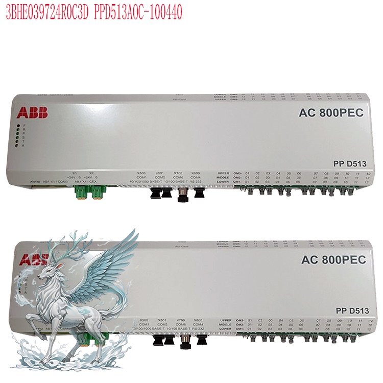
PPD113B03-26-100110 3BHE023584R2634 is the core high-speed central processing unit for synchronous
generator excitation systems
based on the AC800PEC platform. It serves as the master control core of the
UNITROL excitation control system, handling closed-loop excitation regulation,
protection logic, signal acquisition, and external communication.
Signal
Acquisition: The module performs high-speed acquisition of analog and digital
signals—such as generator terminal voltage, stator current, excitation current,
rotor temperature, active/reactive power, and grid frequency. It features a
built-in high-precision ADC to handle signal conditioning, sampling, and
filtering.
High-Speed
Closed-Loop Control Computation: Leveraging the high-speed core of the AC800PEC,
it executes multi-mode control algorithms—including AVR (Automatic Voltage
Regulator) PID control, reactive power regulation, power factor regulation, and
constant excitation current regulation. With control cycles reaching the
microsecond range, it rapidly calculates trigger control commands for the
thyristor rectifier bridge and outputs pulse reference signals to the power
unit. It supports automatic code generation from MATLAB/Simulink models and
allows for the embedding of Power System Stabilizer (PSS) algorithms to suppress
low-frequency oscillations and enhance grid damping. Protection Logic:
Incorporates a comprehensive suite of protection criteria for the excitation
system, including over-excitation, under-excitation, V/Hz limiting, rotor
overcurrent, loss-of-field protection, and load rejection protection. It
performs real-time fault diagnosis and immediately issues trip and
field-suppression commands when protection thresholds are triggered.
Communication
and Data Exchange: Integrates interfaces such as Ethernet, RS232/485, and
Profibus. It communicates upstream with the power plant DCS and HMI to upload
unit operating status and waveform recording data, while interacting downstream
with excitation I/O modules
and power rectifier units. It supports fault recording, capturing waveforms
throughout the entire disturbance process for accident analysis.
Redundancy
Mechanism: Supports a dual-controller redundancy configuration (primary/standby
CPU). In the event of a primary module failure, it performs a bumpless transfer
to the standby module, ensuring uninterrupted excitation regulation and meeting
the requirement that large generator units must not suffer from single-point
failures in the excitation system.
Summary:
Acquires real-time electrical parameters from the generator and grid → Executes
high-speed AVR, PSS, limiting, and protection algorithms → Outputs trigger
commands to control the excitation power circuit → Handles data uploading, fault
alarming, and redundancy switching.
II.
Application Areas
This
module is designed for use with ABB UNITROL excitation systems. Leveraging the
high-speed control capabilities of the AC800PEC, it is primarily used for the
excitation regulation of synchronous generators:
Thermal/Gas
Combined-Cycle Power Plants: Excitation for steam turbine and gas turbine
generators; manages rapid load fluctuations and grid disturbances; ensures
compliance with grid connection codes; utilizes PSS to suppress power
oscillations.
.jpg)
Hydropower
Plants: Hydro-generator units; adapts to variations in water head and severe
load rejection conditions; supports both isolated grid and grid-connected
operation.
Industrial
Captive Power Plants: Synchronous generator units for steel, chemical, and paper
enterprises; ensures stable power supply for plant operations. Diesel
Synchronous Generator Sets: Excitation for large-scale emergency diesel
generators, islanded power supply, and black-start scenarios.
Synchronous
Condensers for New Energy Applications: Excitation control for synchronous
condensers, providing reactive power support and voltage stability for the
grid.
High-Power
Marine Synchronous Generators: Excitation for marine power plants, capable of
handling sudden load fluctuations in shipboard power grids.
Positioning:
Suitable for excitation system retrofits and new installations of
medium-to-large synchronous generators requiring high control response speeds,
reliable protection, and robust grid adaptability.
III.
Environmental Conditions (Cabinet-mounted)
Operating
Temperature: 0°C to +55°C; for long-term full-load operation, keeping the
temperature below 45°C is recommended. Temperatures above 55°C accelerate chip
aging and reduce MTBF; temperatures below 0°C require internal cabinet
heating.
Storage
Temperature: -40°C to +85°C.
Relative
Humidity: 5% to 95%, non-condensing; condensation inside the cabinet is strictly
prohibited, as it can cause short circuits on circuit boards and PCB
corrosion.
Vibration
and Shock: Compliant with IEC 60068; requires reinforced cabinet mounting; avoid
proximity to strong vibration sources such as high-power contactors or rectifier
transformers.
Atmospheric
Environment: The air must be free from corrosive gases (hydrogen sulfide,
chlorine), conductive dust, and salt spray; cabinets located in coastal or
chemical industrial areas require air filtration and salt-spray protection
measures.
Electromagnetic
Environment: Install within a metal control cabinet with reliable grounding;
route wiring separately from thyristor power circuits to avoid strong
electromagnetic interference. Protection Rating: IP20 (for internal cabinet use
only; not suitable for exposed field installation). IV. Module Advantages
High-Speed
Control Performance: The AC800PEC platform features a microsecond-level control
cycle, offering faster response times than traditional excitation controllers.
It delivers superior dynamic voltage performance during grid disturbances and
load rejection events and supports embedded PSS and multi-limiter coordination
algorithms.
Flexible
Control Modes: Supports multiple regulation modes—including constant terminal
voltage, constant excitation current, constant reactive power, and constant
power factor—with seamless switching. It supports model-based development,
enabling automatic control code generation via Simulink and facilitating
convenient algorithm iteration.
Comprehensive
Built-in Protection & Waveform Recording: Includes a full suite of
excitation limiting and protection logic, as well as integrated fault waveform
recording; no additional recording devices are required, simplifying fault
analysis and traceability.
High
Redundancy and Reliability: Supports dual-CPU redundancy and redundant power
supplies with bumpless switchover between primary and backup units, meeting
reliability requirements for critical power plant equipment.
.jpg)
Open
Communication Architecture: Supports multiple protocols, facilitating
integration with DCS, SIS, and power plant monitoring systems for remote
monitoring and parameter tuning.
Modular
Architecture: I/O, communication, and power supply components are independent
modules; localized faults require only the replacement of the specific module,
simplifying maintenance and reducing downtime.
Strong
Grid Adaptability: Meets rigorous domestic and international grid-connection
standards, maintaining unit stability during grid low-frequency oscillations and
voltage dips.
V.
Installation, Commissioning, and O&M Considerations
Hardware
Installation
Modules
must be inserted or removed only when power is disconnected; hot-swapping CPU
boards is strictly prohibited, as it can easily damage the backplane bus and
chips.
Cabinet
grounding must be reliable, utilizing single-point grounding for both protective
earth and signal ground. High-voltage cables (excitation power lines) must be
routed in separate cable trays from low-voltage signal and communication cables
to prevent interference that could cause AVR instability or spurious protection
trips. Ensure module backplanes and terminals are securely fastened; avoid
impacts during transport and installation. Circuit boards are sensitive to
static electricity; anti-static wrist straps must be worn during handling.
Keep
cooling air ducts unobstructed and clean dust filters regularly; continuously
monitor temperature and humidity inside the cabinet to prevent condensation.
Commissioning
and Parameters
Verify
the firmware version before powering up; the version must be compatible with the
entire UNITROL excitation system software suite. Mismatched versions can lead to
communication anomalies and protection logic errors.
Excitation
parameter setting must be performed in stages: first, statically verify
acquisition circuits; next, conduct no-load tests; then, proceed to load tests
and PSS parameter tuning. Strictly prohibit arbitrary modification of protection
settings or AVR parameters while grid-connected, as this can cause generator
instability or over-excitation incidents.
When
commissioning redundant systems, perform separate primary/backup switchover
tests to verify that the switchover process causes no excitation
disturbances.
Operation
and Maintenance
Regularly
check module status indicators to monitor the CPU, power supply, communication,
and fault alarm status; periodically export waveform logs to troubleshoot latent
anomalies.
Circuit
boards are precision electronic components subject to aging during long-term
operation; stock spare parts in advance. Do not use non-OEM refurbished boards
for direct operation.
After
replacing a faulty module, download the project configuration, verify
parameters, and complete functional tests (drive tests); ensure protection and
regulation functions are normal before putting the unit back into service.
Software
modifications and firmware upgrades must be performed while the unit is shut
down or safely isolated; create a full backup of the project program before
upgrading.
Electromagnetic
interference: If voltage sampling fluctuates or random false alarms occur,
prioritize checking shielding grounds and ensuring cable shields are grounded at
a single point; investigate electromagnetic noise originating from the
excitation power cabinet.
Safety
Red Lines
Do
not open the CPU module cover plate while the excitation system is energized or
when the generator is ready for field flashing (excitation startup). Any
modification to protection settings must be carried out in accordance with the
work permit and dual-verification procedures.
If
a module reports a hardware fault, it is recommended to switch to manual
excitation mode or shut down the unit for inspection; prolonged operation with a
known fault is prohibited.
Related
product recommendations:
PPD512A10-15000
3BHE040375R1023
PPD512A10-454000
3BHE040375R103E
PP
D513 A0C-110440 3BHE039724R0C4A
3BHE041576R3011
PPD517A3011
3BHE051476R3011
PPD517
3BHE041576R3011
PPD517
3BHE041576R3011
PPD517
PPD539A
3BHE039770R0102
PPD539A102
3BHE039770R0102
GFD212A
3BHE020357P201
3BHE020356R0101
GFD212
3BHE022294R0101
GFD233
3BHE022294R0103
GFD233
3BHE046836R0101
GFD563
3BHE046836R0102
GFD563A102
ABB
5SHY35L4503
3BHE031197R0001
GBU72
3BHE055094R0002
GBU72
L003748-AR
ABB-3BSX108237R300
5SGY3545L0010
3BHB006485R0001
5SHY35L4503
3BHB004692R0002
More......


 ABB
ABB GE
GE HONEYWELL
 TRICONEX
 KONGSBERG
 EMERSON
 FOXBORO
 MOTOROLA
 VIBRO-METER
 ICS TRIPLEX
 WOODWARD
 BENTLY NEVADA
 OTHER
OTHER Home
Home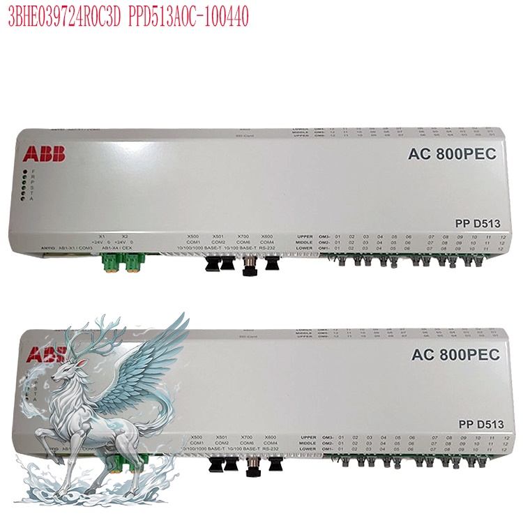
.jpg)
.jpg)