All products on this website are
specialized items subject to fluctuating market prices.
Please rely on the quote provided by
customer service, as the listed prices are not final.
Before placing an order, please confirm
details such as the model, product specifications, and price with customer
service.
Please contact customer service for
inquiries regarding available stock.
PPD103B01 3BHE020455R0001
Alternative Names:
Process
Control
Unit PPD103B01 3BHE020455R0001
PPD103B01 3BHE020455R0001 Central
Processing Unit
AC
800PEC Process Control System PPD103B01 3BHE020455R0001
I.
Operating Principle
This
CPU unit serves as the computational and logic core of the excitation regulator;
together with the data acquisition board, I/O board, and pulse amplification
board, it forms a complete excitation control system.
Signal
Acquisition: Receives generator terminal voltage, stator current, and rotor
current signals from voltage and current transformers; simultaneously acquires
binary signals such as circuit breaker status, raise/lower excitation commands,
and protection contact status.
Closed-loop
Regulation Calculation: Features built-in algorithms for AVR (Automatic Voltage
Regulator), FCR (Field Current Regulator), and PSS (Power System Stabilizer). It
compares the voltage setpoint with the actual terminal voltage in real-time and
outputs control signals via PID calculation.
Pulse
Generation: Converts regulation calculation results into thyristor trigger pulse
commands and transmits them to the pulse board. This controls the conduction
angle of the thyristors within the excitation power cabinet, thereby adjusting
the generator rotor excitation current to achieve stable control of the terminal
voltage. Logic and Protection Processing: Integrates various excitation system
protection logics, including over-excitation, under-excitation, V/Hz limiting,
stator current limiting, rotor overcurrent, and loss-of-field monitoring;
simultaneously handles system status assessment, switching between active and
standby channels, fault alarming, and event logging.
Communication
and Interaction: Communicates via onboard interfaces with the excitation
system's HMI, DCS, and power plant monitoring systems; uploads data such as
excitation current, voltage, fault codes, and operating status, while receiving
remote control commands.
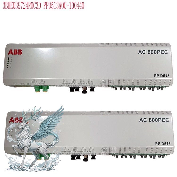
Dual-Channel
Redundancy Mechanism: Typically used in dual-channel excitation systems where
two CPUs serve as backups for each other. When the primary CPU operates
normally, the standby CPU synchronously acquires all signals and tracks the
primary regulator's output; in the event of a primary CPU failure, power
anomaly, or sampling error, the system performs a bumpless transfer to the
standby channel, ensuring uninterrupted excitation operation.
II.
Usage Instructions
Hardware
Installation: Install the board into a standard rack slot within the excitation
control cabinet and secure it firmly; ensure reliable connection of the
backplane bus connector; connect external sampling cables, discrete signals, and
communication cables to the corresponding terminals according to the schematics,
ensuring separate routing for high-voltage and low-voltage lines to prevent
interference.
Pre-power-up
Checks: Verify the supply voltage and inspect the backplane for short circuits
or loose wiring; confirm that instrument transformer secondary circuits are free
of open circuits and properly grounded; verify that DIP switch settings and
hardware addresses are configured according to project schematics.
Power-up
and Startup: Apply auxiliary power first; upon power-up, the CPU executes a
self-test routine. The self-test covers memory, firmware, A/D sampling circuits,
bus communication, and board hardware. If the self-test passes without
anomalies, the system enters standby mode; if it fails, the corresponding fault
LED illuminates, and the fault event is logged. Parameter Configuration: Connect
to the CPU via the excitation HMI panel or host software to input unit
parameters: generator rated voltage, rated rotor current, transformer ratios,
PID parameters, limit curves, protection settings, PSS parameters, communication
addresses, and channel switching logic. Parameters are downloaded to the CPU's
flash memory for permanent storage.
Static
Commissioning: With the unit stationary, apply simulated voltage and current
signals to verify sampling accuracy; test AVR regulation response, field
boosting/bucking, limiting functions, and protection logic; and verify the
dual-channel switching function.
Grid
Connection and Operation: Before field flashing, set the CPU to automatic AVR
mode; during field flashing, the CPU automatically regulates excitation to
establish terminal voltage; after grid connection, maintain constant terminal
voltage and respond to system voltage fluctuations; switching to manual FCR
(rotor current regulation) mode is supported.
III.
Operation Methods
1.
Mode Switching
Automatic
AVR Mode: Default operating mode, regulating based on terminal voltage.
Switching can be performed via the local panel or remotely via DCS.
Manual
FCR Mode: Regulates based on rotor current; generally used for testing or fault
conditions; long-term grid-connected operation in this mode is not
recommended.
Channel
Switching: Supports automatic fault-based switching as well as locally triggered
manual switching tests between main and standby channels.
2.
Field Boosting/Bucking Operations
Local
Operation: Issue field boost or buck commands via the excitation panel; commands
are transmitted to the CPU, which modifies the voltage setpoint and adjusts the
excitation output. Remote Operation: The DCS system issues field boost/buck
commands via communication; the CPU receives and executes them while applying
command interlock logic (preventing further adjustment if limits are
exceeded).
.jpg)
3.
Parameter Operations
Parameter
Reading: Connect using host software tools to read operating parameters, event
waveforms, and fault records from the CPU. Parameter Modification: Requires
engineer-level privileges. After modification, download the parameters to the
CPU and save them; some critical parameters require a board reboot to take
effect.
Waveform
Retrieval: The CPU features built-in fault waveform recording; it automatically
captures waveforms during excitation disturbances, trips, or faults for
post-event analysis.
4.
Fault Reset Operation
Once
the fault is cleared, a reset command can be issued via the local panel or
remotely; the CPU clears the fault alarm and resumes normal monitoring. If a
persistent hardware fault exists, the reset cannot be performed.
IV.
Precautions
Power
Supply: The board operates on 24V DC; power fluctuations must remain within
permissible limits. A UPS is recommended to prevent voltage dips from damaging
the board. Reverse polarity connection is strictly prohibited.
Electromagnetic
Protection: Ensure the control cabinet is reliably grounded and shielded cables
are grounded at one end. Route high-power lines in the power cabinet separately
from low-voltage CPU sampling lines to prevent electromagnetic interference
(generated by thyristor switching) from causing sampling distortion or control
errors.
Electrostatic
Protection: Wear an anti-static wrist strap when installing or removing boards;
do not touch chips or gold-plated edge connectors with bare hands, as static
electricity can instantly destroy the CPU chip. Store boards in anti-static
bags.
Channel
Maintenance: During dual-channel operation, do not remove both CPU boards
simultaneously. Shut down the system or implement appropriate safety measures
before replacing boards; after replacement, verify the firmware version and
project parameters, and perform recalibration.
Firmware
Version: When replacing a CPU, flash it with a firmware version compatible with
the original system; version mismatches can lead to communication anomalies,
control logic errors, or failure of channel switching.
Parameter
Management: Maintain backup files for all parameter modifications. Do not
arbitrarily modify PID settings, limits, or protection setpoints while the unit
is running, as this could cause unit oscillation or over-excitation trips.
Operational Monitoring: Regularly monitor the status indicator lights on the
boards; promptly check the event log if a red fault indicator illuminates. CPU
overheating will trigger an alarm; inspect the cabinet fans and temperature
control system.
Safety
Isolation: During maintenance, ensure the board's power supply and the CT
secondary circuit are disconnected to prevent high voltage from entering the
board, which could cause equipment damage or personal injury.
V.
Application Areas
Thermal
Power Units: Serves as the main controller for the UNITROL excitation system in
steam turbine generators—its primary application scenario.
Hydropower
Units: Excitation regulation for large and medium-sized hydro-generators,
meeting the rapid response requirements of hydraulic turbines.
Gas
Turbine Power Projects: Excitation control for generators in combined-cycle
power plants.
.jpg)
Captive
Power Plants: Internal generator units for steel, chemical, and large-scale
petrochemical enterprises.
New
Energy-Supporting Peak-Shaving Plants: Excitation control for synchronous
generators in peak-shaving plants, supporting grid voltage stability.
Overseas
Power Projects: Excitation control systems for export-oriented generator unit
packages.
VI.
Advantages and Features
High-Performance
Computing: Features high-speed sampling and short control cycles; the AVR offers
rapid regulation response and strong voltage fluctuation suppression, ensuring
high stability during system disturbances.
Reliable
Redundant Architecture: Supports dual-CPU redundancy with bumpless channel
switching; a single CPU failure does not trip the excitation system,
significantly enhancing the unit's continuous operation capability.
Comprehensive
Limiting and Protection Algorithms: Includes a full suite of built-in generator
excitation limit models—such as V/Hz, over-excitation, under-excitation, and
stator current limits—to prevent operation outside permissible ranges under
various conditions. Integrates PSS (Power System Stabilizer) to effectively
suppress low-frequency power system oscillations.
Powerful
Event Logging and Waveform Recording: Large-capacity event logging with
millisecond-level timestamps; built-in fault recording captures voltage,
current, and control signals, facilitating fault tracing and analysis.
Versatile
Communication Interfaces: Supports multiple industrial communication protocols
for easy integration with power plant DCS and SCADA systems, ensuring stable
data exchange.
Modular
Design: Features independent circuit boards for easy replacement and
maintenance; part of the UNITROL standard module series with a mature spare
parts ecosystem.Strong interference immunity: Industrial-grade hardware design
and wide operating temperature range make it suitable for power plant
environments characterized by dust, vibration, and strong electromagnetic
interference.
High
configurability: Control logic, protection settings, and regulation parameters
can all be configured via software, allowing adaptation to generators of various
capacities and types, as well as flexible project implementation.
PPD103B01 3BHE020455R0001
CPU Closed-Loop Regulation Calculation Process
I.
Signal Acquisition and Pre-processing Stage (Pre-calculation phase)
The
onboard A/D sampling circuit continuously acquires generator terminal PT
voltage, stator CT current, and rotor excitation current (from the power cabinet
shunt); simultaneously, it acquires binary signals such as generator circuit
breaker position, unit status, and channel status. The sampling cycle is fixed
by the CPU firmware, utilizing high-speed synchronous sampling to ensure phase
alignment between voltage and current.
Signal
per-unit (p.u.) conversion: The CPU converts raw A/D values into per-unit (p.u.)
values based on project-preset PT and CT transformation ratios; all subsequent
regulation calculations are based on this per-unit model.
Signal
validation and filtering:
Validity
check: Detects sudden jumps, wire breaks, or out-of-range conditions in
voltage/current signals. If a PT wire break is detected, the PT wire break logic
is automatically triggered, the AVR is blocked, and the system can automatically
switch to FCR (manual) mode.
Digital
filtering: FIR digital filtering is employed to eliminate high-frequency noise
caused by electromagnetic interference, preventing jitter in the regulation
output; filtering parameters are configurable.
Calculation
of auxiliary variables: Generator active power, reactive power, and power factor
are calculated from terminal voltage and stator current for use in the PSS,
under-excitation/over-excitation limiting, and stator current limiting
modules.
Upon
completion of pre-processing, the following values are obtained—actual terminal
voltage (Ut_act), actual rotor current (If_act), active power (P), and reactive
power (Q)—and are fed into the closed-loop regulation module.
II. Setpoint Generation Stage (Closed-loop Setpoint)
In
AVR mode, the priority for the voltage setpoint (Ut_ref) source is: Remote DCS
setpoint > Local panel setpoint > Local raise/lower excitation operation.
Raise/lower operations essentially involve slowly modifying Ut_ref subject to a
rate-of-change limit (to prevent large excitation fluctuations caused by sudden
setpoint jumps). The setpoint is also subject to hard upper and lower limits,
ensuring it does not exceed the unit's permissible maximum and minimum terminal
voltage settings.
III.
Outer Loop: AVR Voltage Closed-loop Calculation (Main Regulation
Loop)
AVR
Objective: To maintain the generator terminal voltage (Ut) so that it tracks the
setpoint (Ut_ref).
Deviation
Calculation:
\(e_{Ut}=U_{t\_ref}-U_{t\_act}\)
where \(e_{Ut}\) is the voltage deviation, Ut_ref is the voltage setpoint, and
Ut_act is the measured terminal voltage. 2. PID Calculation (UNITROL employs an
incremental PID algorithm with integral anti-windup; this is the core algorithm
for this CPU).
P
(Proportional) Term: Outputs a regulation value directly based on the magnitude
of the deviation, enabling rapid response to voltage deviations; the
proportional gain (Kp) is configurable.
I
(Integral) Term: Eliminates steady-state voltage error. It includes integral
anti-windup (back-calculation); integration accumulation pauses when the output
is clamped, preventing integral saturation that could lead to regulation
overshoot. This is a critical design feature of the excitation regulator,
preventing voltage oscillations during major disturbances.
D
(Derivative) Term: Suppresses dynamic fluctuations caused by rapid voltage
changes and dampens oscillations; the D term is generally small and may be set
to zero under certain operating conditions.
AVR
Outer Loop Output: The AVR PID output serves as the setpoint (If_ref) for the
inner rotor current loop.
Simplified
Concept: The voltage outer loop calculates the amount of rotor current required
to bring the terminal voltage back to the setpoint and outputs this value to the
inner rotor current loop. IV. Inner Loop: FCR Rotor Current Closed-Loop
Calculation (Current Inner Loop)
The
current inner loop responds much faster than the voltage outer loop, functioning
as a high-speed servo loop. Its role is to precisely track the rotor current
setpoint ($I_{f\_ref}$) issued by the AVR outer loop and to reject disturbances
in the excitation power circuit (such as power supply fluctuations or variations
in thyristor voltage drops).
V.
Limiter Module Intervention (Priority Higher Than Standard PID
Regulation)
While
the dual-loop system operates normally, the CPU simultaneously runs various
limiters. These limiters function as protective closed-loop controls with higher
priority than standard AVR/FCR regulation. If the operating point reaches a
limit boundary, the limiter takes over the regulation setpoint, forcing the unit
back into the safe operating zone; the AVR is simultaneously locked out by the
limiter. The parallel limiter loops include:
Over-Excitation
Limiter (OEL): Monitors generator rotor current; if the current exceeds limits,
the OEL output overrides the AVR setpoint to reduce excitation current and
protect the rotor from overheating.
Under-Excitation
Limiter (UEL): Monitors active power and terminal voltage; if the unit enters an
excessive leading power factor (underexcited) state, the UEL increases
excitation to prevent loss of excitation.
V/Hz
Limiter (Flux Limiter): If the voltage-to-frequency ratio exceeds limits, the
voltage setpoint is reduced to prevent over-fluxing of the generator stator
core.
Stator
Current Limiter (SCL): If stator current exceeds limits, excitation is reduced
to limit stator heating.
Limiters
also utilize independent PID closed-loop calculations; once activated, they
directly override the AVR outer loop output ($I_{f\_ref}$) to prioritize
protective regulation. Upon deactivation, the system smoothly reverts to AVR
regulation.
VI.
PSS Power System Stabilizer Parallel Operation (Supplementary Damping Branch;
Does Not Replace Main Closed-Loop)
The
PSS provides a supplementary control signal and does not participate in the
basic regulation of the main voltage closed-loop. The CPU acquires active power
(P) or rotor speed signals. After passing through DC-blocking and lead-lag
compensation stages, it generates an auxiliary PSS output (ΔUp), which is
superimposed onto the AVR voltage reference (Ut_ref). Function: When
low-frequency oscillations occur in the power grid, the PSS outputs an auxiliary
excitation modulation signal to introduce positive damping into the system,
thereby suppressing generator power oscillations. The PSS output is subject to
maximum amplitude limiting, ensuring it does not cause significant disturbances
to the generator terminal voltage reference.
VII.
Output Limiting, Channel Processing, and Pulse Command Issuance
Hard
limits are applied to the final firing angle command: minimum and maximum firing
angles are set to ensure the thyristors operate within a safe range.
Dual-channel
redundancy processing: The primary CPU performs the complete closed-loop
calculation and outputs firing commands; the standby CPU performs synchronous
sampling and executes the same closed-loop calculation, tracking the primary
channel's output in real-time. In the event of a primary CPU failure, a bumpless
transfer occurs, and the standby CPU's calculation results directly take over
pulse output.
The
CPU transmits the calculated firing angle commands via the internal bus to the
pulse amplification board. Based on the firing angle, the pulse board generates
synchronized thyristor firing pulses to drive the thyristors in the excitation
power
cabinet.
VIII.
Feedback Update and Cyclic Calculation
The
power cabinet executes the firing command → rotor excitation current changes →
generator magnetic field changes → generator terminal voltage (Ut) changes → new
voltage and current signals are fed to the CPU's sampling inputs, initiating the
next closed-loop calculation cycle. This closed-loop process repeats
continuously.
IX.
Closed-Loop Calculation in Manual FCR Mode (Current-Only Closed-Loop; AVR Outer
Loop Disabled)
When
switched to manual FCR mode, the AVR voltage outer loop is completely disabled.
The setpoint becomes the rotor current reference (If_ref), and the CPU executes
only the rotor current inner-loop PID control to maintain a constant rotor
current. In this mode, the terminal voltage varies with the generator load;
there is no automatic voltage regulation capability, and the mode is used only
for testing or as a backup during AVR failure.
X.
Key Characteristics of Closed-Loop Computation (CPU Firmware
Features)
Multi-loop
timing: The outer voltage loop operates on a slower cycle, while the inner rotor
current loop operates on a faster cycle; decoupling the fast and slow loops
ensures stability.
Integral
anti-windup is central: When a limiter activates or the output reaches its
limit, integral accumulation halts to prevent significant voltage overshoot the
moment the system exits the limiting state.
Smooth
switching logic: During AVR↔FCR transitions or main/standby channel switching,
the CPU performs output tracking to ensure there are no abrupt changes in the
control signal at the moment of transfer, thereby achieving bumpless
switching.
All
intermediate variables in the computation process (error, PID output, PSS
output, limiter status) are stored in memory in real-time to serve as event
recording data.
Recommended
related products:
3BHE030410R3011
PPD113
PPD113B03
3BHE030410R3011
PPD113B03-20-110110
3BHE023584R204Z
3BHE023584R204Z
PPD113
PPD113B01-10-150000
3BHE023784R1023
PPD113B03-26-100110
3BHE023584R2634
3BHE023584R2634
PPD113
PPD113B01-25-111000
3BHE023784R2530
3BHE023784R2530
PPD113
3BHE017628R0002
PPD115
3BHE017628R0102
PPD115
PPD115A102
3BHE017628R0102
PPD117A3011
3BHE030410R3011
3BHE040375R1023
PPD512
PPD512A10-15000
3BHE040375R1023
PPD512A10-454000
3BHE040375R103E
3BHE039724R0C4A
PP D513A0C
PP
D513 A0C-110440 3BHE039724R0C4A
PPD513
A0E-110110 3BHE039724R0E41
3BHE039724R0E41
PPD513
More......


 ABB
ABB GE
GE HONEYWELL
 TRICONEX
 KONGSBERG
 EMERSON
 FOXBORO
 MOTOROLA
 VIBRO-METER
 ICS TRIPLEX
 WOODWARD
 BENTLY NEVADA
 OTHER
OTHER Home
Home
.jpg)
.jpg)