Many products are not yet listed online; please contact us for more
information.
If the product model differs from the displayed image, the model number
takes precedence. Please contact us for specific product photos; we can arrange
for warehouse staff to take and verify them.
We operate 76 shared warehouses globally, so it may sometimes take a few
hours to provide you with an accurate response; we appreciate your
understanding. Rest assured, we will address your inquiries as quickly as
possible.
3BHE022291R0101 Alternative Names:
Excitation Controller Module 3BHE022291R0101
3BHE022291R0101 Unitrol Exciter Control Unit
Central Excitation Processing Unit 3BHE022291R0101
I. Operating Principle
The 3BHE022291R0101 is a module based on a heterogeneous, high-speed
cooperative control architecture. It works in conjunction with the AC800PEC
hardware suite to execute complete excitation and power electronics closed-loop
control.
1. Hardware Architecture: The module integrates a communication processing
unit, a logic processing unit, a fiber-optic interface unit, and signal
conditioning circuitry. On one hand, it receives real-time field signals—such as
generator voltage, current, rotor operating conditions, and switch
statuses—collected by other excitation system boards, performing signal
isolation, filtering, and analog-to-digital conversion. On the other hand, it
exchanges data bidirectionally with the processor unit and power drive unit via
a high-speed fiber-optic bus, enabling the rapid issuance of commands and
feedback of status information.
2. Control Logic: Acting as a central control bridge, the module uploads
collected field data to the main controller and receives the results of
regulation algorithms calculated by the controller. It then outputs pulse
control commands to the power unit, thereby achieving closed-loop regulation of
the generator excitation. It features built-in hardware-level fault detection
logic that monitors hardware links, communication status, and signal anomalies
in real-time. Upon detecting faults such as overvoltage, communication
interruption, or signal loss, it rapidly outputs protection signals to trigger
system alarms and lockout protection.
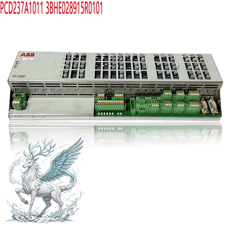
3. Communication Interaction Principle: The board integrates high-speed
Ethernet and fiber-optic interfaces. Internally, it enables high-speed,
real-time data exchange between modules within the same rack. Externally, it
interfaces with DCS systems, HMIs, and backend monitoring systems to upload
operating parameters and fault codes, receive remote commands, and ensure the
coordinated operation of the entire system.
4. Redundancy Principle: It supports a dual-module hot-standby redundancy
architecture. Two 3BHE022291R0101 units operate in parallel; the primary module
performs the active work while the standby module synchronously tracks all
operational data. In the event of a hardware failure or communication anomaly in
the primary module, the system performs a bumpless automatic switchover to the
standby module, ensuring uninterrupted excitation system operation and
preventing unplanned unit shutdowns.
II. Core Product Advantages
1. Highly Integrated Design: High-speed communication, signal processing,
link management, and fault monitoring functions are integrated onto a single
board. This reduces intermediate interface hardware, simplifies system
architecture, minimizes potential points of failure, and reduces the
installation footprint within the control cabinet, meeting the requirements for
compact excitation cabinet layouts.
2. High-Speed Real-Time Data Processing: The system supports
microsecond-level control cycles typical of power electronics and utilizes a
high-speed fiber-optic serial bus. With low data transmission latency, it meets
the real-time requirements for rapid voltage regulation, forced excitation, and
fast fault protection in generator excitation systems, ensuring a rapid dynamic
response from the unit. 3. Robust redundancy and fault tolerance: Native support
for dual-controller hot-standby redundancy ensures bumpless primary-to-backup
switching. Comprehensive self-diagnostic capabilities identify board-level
faults, fiber-optic link failures, and signal anomalies, outputting precise
error codes to facilitate rapid troubleshooting by O&M personnel and
significantly enhancing the continuous operational reliability of power
generation equipment.
4. Multi-protocol compatibility and strong system adaptability: Equipped
with multiple Ethernet and fiber-optic interfaces, the system supports
Industrial Ethernet and fieldbus protocols, enabling seamless integration with
mainstream DCS, PLC, and backend monitoring platforms. It is suitable for both
new UNITROL 6000 excitation system installations and the retrofit/replacement of
legacy excitation systems, offering excellent hardware compatibility.
5. Industrial-grade hardware for harsh operating conditions: Designed with
wide-temperature hardware, the system offers resistance to vibration and
electromagnetic interference (EMI), making it suitable for the high-EMI
environments found in power plants and industrial converter sites. All board
signals are electrically isolated, effectively preventing module malfunctions or
damage caused by high-voltage interference in the field.
.jpg)
6. Easy maintenance and fault traceability: Modules support hot-swapping
and rack-mount installation. Upon failure, the system records fault sequences
and error codes to facilitate post-incident analysis and equipment servicing;
simple spare-part replacement minimizes downtime for maintenance.
III. Relevant
Industries and Practical Applications
The 3BHE022291R0101 module is primarily designed for use with the ABB UNITROL 6000 excitation system, serving the power generation and industrial
high-power power conversion sectors. Its specific functions across these
industries are as follows:
1. Thermal and Hydroelectric Power Generation
Function: Acts as the core communication and control board for the
excitation system, enabling closed-loop excitation regulation to stabilize
generator terminal voltage and reactive power. It provides rapid protection
during fault conditions, ensuring the safe and stable grid-connected operation
of steam and hydro turbine generators. It also supports communication with power
plant DCS (Distributed Control Systems) for remote monitoring and parameter
downloading, serving as critical hardware for safe grid integration.
2. New Energy Power Generation (Concentrated Solar Power Plants,
Large-scale Energy Storage/Peak-Shaving Plants)
Function:Used for excitation control in synchronous condensers and energy
storage power conversion systems. It supports grid voltage regulation and
reactive power compensation, enhances grid-connection stability for new energy
plants, helps manage grid disturbances, and ensures the reliable operation of
on-site equipment.
3. High-Power Rectification Systems for Metallurgical Electrolysis
Function: Utilized in high-power thyristor rectification control systems to
manage signal exchange and logic protection for rectification equipment. It
stabilizes DC output to support energy-intensive industrial processes—such as
electrolytic aluminum and chemical electrolysis—ensuring the stability of
production process parameters.
4. High-Power Power Generation and Conversion Systems for Marine and Rail
Transit
Function: Controls excitation for marine synchronous generators and
auxiliary power generation systems in locomotives. It facilitates high-speed
control communication in environments characterized by high vibration and space
constraints, ensuring the reliable operation of mobile power generation
equipment. 5. Industrial Large-Scale Synchronous Motor Drive Applications
Excitation control systems for large synchronous motors and synchronous
compressors; enables motor field excitation, voltage regulation, and
loss-of-field protection, ensuring the stable operation of large-scale
industrial drive equipment.
Summary of Overall Industry Value: This module ensures high-speed,
reliable, and redundant operation of excitation/converter systems for high-power
synchronous equipment. It reduces the risk of unit failure and downtime,
enhances the operational stability of the power grid and industrial equipment,
and minimizes economic losses caused by unplanned outages.
IV. Standard Operating Procedures
Important Note: Module operations must be performed by certified electrical
technicians familiar with the UNITROL 6000 excitation system, in strict
accordance with the original manufacturer's technical manual.
4.1 Installation Procedures
1. Power-Off Verification: Ensure the cabinet is completely powered down;
verify that both AC and DC power supplies are disconnected and discharge any
residual energy within the cabinet. Wear an anti-static wrist strap to prevent
electrostatic discharge (ESD) from damaging board chips. 2. Rack Positioning:
Smoothly slide the 3BHE022291R0101 module into the slot along the rack guide
rails; ensure it is fully seated in the slot and tighten the upper and lower
mounting screws. 3. Cable Connection: Connect the fiber-optic communication
cables, Ethernet cables, and backplane connectors in sequence. Handle
fiber-optic connectors with care to avoid scratching the end faces or
contaminating them with dust; ensure all connectors are fully locked in place.
4. Redundant Configuration: For dual-redundant configurations, install the two
modules in their designated slots and connect the primary-standby communication
fiber-optic cables according to the schematics. 5. Hardware Inspection: Re-check
all wiring to ensure there are no loose or incorrect connections and that no
cables are pressing against the circuit boards.
.jpg)
4.2 Power-up and Configuration
Download
1. After confirming the hardware is correctly installed, power up the
cabinet step-by-step; observe the status indicator lights on the module panel
and verify that the power indicator is lit. 2. Use the Control Builder M
engineering software to establish the hardware configuration; select the
specific hardware model (3BHE022291R0101) and verify the firmware version. The
firmware version must match the version of the entire system; a mismatch will
result in system errors and operational failure. 3. Download the project
configuration to the controller and complete the module parameter settings,
including communication address, redundancy mode, fault thresholds, and signal
logic parameters. 4. System self-test: Wait for the unit's self-test to
complete; ensure there are no red alarm lights on the module and that the
communication link status appears normal.
4.3 Commissioning and Operation
1. No-load test: With the unit in a non-excited state, test communication
between the module, controller, I/O boards, and the upper-level DCS; verify that
uploaded signal values match actual field readings; simulate fault points to
verify that protection logic triggers correctly. 2. On-load trial run: After the
unit is put into operation, continuously observe the module's running indicator
lights and monitor fault alarm information; record the module's communication
status. 3. Redundancy switchover test (optional): During a maintenance window,
simulate a primary module failure to verify the automatic switchover function
between primary and backup modules, ensuring there is no disturbance to the unit
during the switchover process.
4.4 Removal and Replacement
1. Reduce system power output and shut down the unit if conditions permit;
for redundant systems, faulty boards can be replaced via online hot-swapping,
though close monitoring of the operational status is recommended. 2. Wear an
anti-static wrist strap, loosen the module's mounting screws, disconnect the
fiber optic and network cable connectors, and then smoothly slide the module out
along the guide rails; do not pull the module out by tugging on the cables. 3.
Refer to the installation procedure when installing new spare parts. After
replacement, verify the firmware, download the original backup parameters, and
test communication and protection functions to ensure proper operation before
putting the unit into service.
V. Precautions
5.1 Electrostatic Discharge (ESD) Precautions
1. Circuit boards are precision electronic components; a certified
anti-static wrist strap must be worn throughout the handling process. Do not
touch chips or gold-finger contacts directly. Use anti-static packaging bags for
module storage and transport. Static electricity can cause latent damage to the
module, leading to random failures later despite initial normal operation.
5.2 Firmware and Version Matching
1. When replacing a module, the firmware version must match that of the
original excitation system. Version mismatches can cause serious issues such as
communication interruptions, failure to download parameters, corrupted
protection logic, and abnormal unit operation. Always verify the firmware
version number before replacement and prioritize importing the original system's
backup parameter file.
5.3 Fiber Optic Cable Handling
1. Do not touch the end faces of fiber optic connectors; if contaminated
with dust, clean them using specialized fiber optic cleaning tools. Avoid
excessive bending of fiber optic cables and adhere to the minimum bending radius
specified in the manual. Ensure connectors are fully seated; loose connections
can cause packet loss and random communication failures.
5.4 Environmental and Installation Requirements
1. The control cabinet housing the module must be kept dry and
well-ventilated, free from corrosive gases and dust accumulation. Strictly
adhere to the manufacturer's specifications for operating temperature and
humidity. Avoid installing the module near sources of strong electromagnetic
interference, such as high-power contactors or thyristors. Ensure a reliable
cabinet grounding system with grounding resistance compliant with electrical
standards to minimize the impact of electromagnetic interference.5.5 Safety
Precautions for Live Operations
1. For non-redundant systems, hot-swapping modules is strictly prohibited,
as it will directly cause system downtime. Even for redundant systems that
support hot-swapping, online replacement must be performed only by qualified
personnel; the unit's operating status must be closely monitored during the
replacement process, and operations must cease immediately if any abnormalities
occur. 2. High-voltage circuits exist inside the cabinet; strictly adhere to
high-voltage safety protocols when opening the cabinet to prevent electric shock
accidents.
5.6 Routine Maintenance Precautions
1. Periodically inspect module indicator light statuses and record alarm
codes; regularly check connectors and optical fibers for looseness or dust
accumulation. 2. Do not arbitrarily modify low-level module parameters; always
create a full backup of project files before modifying any parameters. 3. If a
module reports a fault alarm, do not attempt to mask the issue by repeatedly
restarting the unit; instead, troubleshoot the communication links and external
signals based on the fault code, and confirm that all external components are
functioning correctly before concluding that the board itself is damaged. 4.
Store spare parts in a dry, dark environment, avoiding high temperatures and
humidity; keep long-term idle boards in their anti-static packaging.
5.7 Prohibitions Regarding Fault Handling
If a module malfunctions, do not disassemble the board yourself; there are
no user-serviceable parts inside, and unauthorized disassembly renders the spare
part unusable. Contact a professional automation service provider to inspect and
handle faulty hardware.
Conclusion
The 3BHE022291R0101 AC 800PEC control communication module
is an indispensable core component of the UNITROL 6000 excitation system.
Hardware performance, installation and commissioning, version compatibility, and
operation and maintenance practices directly determine the safety and stability
of the entire generator excitation system. In applications involving power
generation, new energy, and metallurgical synchronization equipment,
standardized operation and regular inspections maximize the advantages of
high-speed control with modular redundancy, ensuring the long-term, stable
operation of the equipment.
Recommended related products:
3BHE032025R1101 PCD235
PCD235 3BHE057901R0101
3BHE057901R0101 PCD235C101
3BHE028915R0101 PCD237A1011
3BHE028915R0101 PCD237A1011
3BHE041343R0102 PCD530A
PPD103B101 3BHE020455R0101
3BHE02384R2630 PPD103
3BHE020455R0101 PPD103B
3BHE020455R0001 PPD103
3BHE020455R0103 PPD103
PPD113B03 3BHE030410R3011
PPD113B01-10-150000 3BHE023784R1023
3BHE023784R2530 PPD113
More......


 ABB
ABB GE
GE HONEYWELL
 TRICONEX
 KONGSBERG
 EMERSON
 FOXBORO
 MOTOROLA
 VIBRO-METER
 ICS TRIPLEX
 WOODWARD
 BENTLY NEVADA
 OTHER
OTHER Home
Home
.jpg)
.jpg)


.jpg)
.jpg)