Many products are not yet listed. Please
contact us for more information.
If the product model differs from the
displayed image, the model number shall prevail. Please contact us for specific
product images; we will arrange to take photos in our warehouse for
confirmation.
We have 76 shared warehouses worldwide,
so it may sometimes take several hours to accurately return the information to
you. We apologize for any inconvenience. Of course, we will respond to your
inquiries as soon as possible.
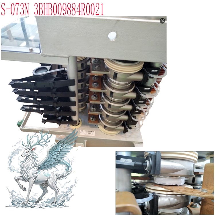
S-073N 3BHB009884R00211
Other Names:
High
Voltage Power Electronic Phase Module S-073N 3BHB009884R00211
S-073N 3BHB009884R00211 ACS
6000 Medium Voltage Driver
PCS
6000 Advanced Console Server S-073N 3BHB009884R00211
I.
Functions
This
rack is the core of the ACS6000 system's power conversion,
undertaking the following functions:
First
Layer: Power Form Conversion
The
rack internally houses multiple IGCT (Integrated Gate Commutated Thyristor)
power modules, models 5SHY3545L0016 and 5SHY4045L0006.
Each IGCT module,
in conjunction with anti-parallel diodes, forms a complete power switching pair.
The PPD517A3011 pulse
distribution board within the rack receives PWM commands from
the PM645B controller
and precisely controls the on/off state of each IGCT according to the switching
sequence of the three-level topology. The DC bus voltage (typically 2300V to
4160V, depending on the system voltage level) is cut by the IGCT modules
according to a sinusoidal PWM pattern, synthesizing a three-phase stepped
multi-level output voltage. The equivalent sinusoidal distortion (THD) of this
output voltage is typically below 5%, far superior to the 15% to 20% of
traditional two-level inverters. Therefore, motor-side harmonic losses are
significantly reduced, motor temperature rise is lower, and insulation life is
longer.
.jpg)
Second
Layer: Direct Torque Control (DTC)
The
ACS6000 uses ABB's patented Direct
Torque Control algorithm,
rather than traditional vector control. DTC achieves high-precision torque
control without the need for resolver or encoder feedback. The PM645B controller
calculates the actual values of stator flux and electromagnetic torque every 25
microseconds and compares them with the given values. It directly selects the
optimal IGCT switching state using a hexagonal flux meter and torque comparator.
This means the delay from a given torque change to the actual torque response is
only 1 to 2 milliseconds, far faster than the 10 to 20 milliseconds of vector
control. For operating conditions requiring extremely high instantaneous torque,
such as starting up a ball mill in a mine or during the moment of steel biting
in a rolling mill, the advantages of DTC are extremely obvious.
Third
Layer: Power Unit Level Management and Redundancy
The
rack does not contain only one IGCT module, but rather multiple power units
connected in series. Each power unit includes a set of IGCT modules, a set of
driver boards PPD512A10-45400
or PPD513AOC-100440, and a set of voltage detection circuitry. The pulse
distribution board PPD517A3011 is responsible for distributing the unified PWM
signal from the controller to the driver boards of each power unit. When the
IGCT module of a power unit fails, the driver board of that unit will
automatically block its output in the next switching cycle. The PM645B
controller then recalculates the switching sequence of the remaining units, and
the system automatically operates at reduced derating. In a typical
configuration, even after losing one unit, the system can still output over 90%
of its rated power without shutting down. This is significant for continuous
production enterprises (such as steel mill rolling lines and main conveyor belts
in mines), preventing huge economic losses caused by unplanned downtime.
Fourth
Layer: Signal Acquisition and System Protection
The
voltage detection board PVD164A2059 acquires
the DC bus voltage, output voltage of each phase, and output current in real
time. The acquired data is used for closed-loop feedback of the DTC algorithm
and for triggering protection logic. Protection includes, but is not limited to:
DC overvoltage protection (tripping when the bus voltage exceeds the threshold
due to braking energy feedback), AC overcurrent protection (tripping when the
output current exceeds 150% of the rated value for 200 milliseconds), IGCT
overtemperature protection (derating when the temperature exceeds 55°C and
tripping when the temperature exceeds 65°C, monitored by a water-cooled
temperature sensor), and water-cooled fault protection (immediately tripping and
blocking the IGCT when the water flow rate is lower than the set value or the
water temperature exceeds 45°C). All protection actions are uploaded to the
control unit and output to the DCS system via the GFD563A101 and GFD563A102 I/O modules.
.jpg)
Layer
: Communication and External Interfaces
The
rack provides a Profibus DP interface via the CI858K01 module, a Modbus TCP/IP
interface via the CI867AK01 module,
and an RS232/RS485 serial port via the PCD232 module.
These interfaces allow the upper-level DCS or PLC to
read real-time data such as the rack's operating status, fault codes, and motor
current and voltage, and to issue start/stop commands, speed commands, and
torque commands. Communication latency under Profibus DP is typically less than
10 milliseconds, meeting real-time control requirements.
Layer
: Excitation Control (When Configured with a Synchronous Motor)
When
driving a synchronous motor, the integrated excitation control board
PFSA140RULLM7A and excitation controllers PM891/PM891K01/PM891K02 within
the rack are responsible for providing adjustable DC excitation current to the
motor rotor. The magnitude of the excitation current directly affects the
motor's power factor. By adjusting the excitation, the synchronous motor can
operate with a leading power factor, feeding reactive power back to the grid,
improving the overall power factor of the plant, and reducing the investment in
reactive power compensation capacitors. This is particularly important in
large-scale fan and pump applications in the power industry.
Multi-level
PWM Output: Employing a three-level topology, it outputs a near-sine wave
multi-level PWM voltage, significantly reducing motor harmonic losses and dv/dt
stress.
Real-time
Control Execution: Receives torque and flux commands from the upper-level
controller (PM645B/PM644,
etc.) and controls the on/off timing of the IGCT via the drive board
(PPD517A3011 pulse distribution board, PPD512A10/PPD513AOC
power unit drive board).
Voltage
and Current Detection: Real-time acquisition of DC bus voltage and output
voltage via the PVD164A2059 voltage
detection board, feeding back to the controller for closed-loop regulation.
Section
Excitation
Control Support: The rack can be configured with PFSA140/PM891/PFSA140RULLM7A
excitation control boards to provide excitation current to the synchronous
motor.
II.
Usage Method:
System
Configuration: This rack is part of the INU (Inverter Unit) in the standard
single-drive configuration of the ACS6000 system. It needs to be used in
conjunction with LSU (Linear Power Supply Unit/12-Pulse Rectifier), ARU (Active
Rectifier Unit, optional), TEU (Termination Unit), CBU (Capacitor Bank Unit),
WCU (Water Cooling Unit), and COU (Control Unit) to form a complete drive
system.
Software
Tools: Parameter settings and debugging require ABB Control Builder or
Automation Builder engineering software. Connection is required via a fiber
optic programming tool (RUSB-02 or PCMCIA equivalent). Laptops must have
DriveDebug and DriveWindow pre-installed.
Phase
One: Installation and Wiring:
After
the rack arrives on site, first confirm that the rack model matches the order
form and check for any collision damage during transportation. The rack should
be installed in a closed metal cabinet. The cabinet dimensions must meet the
installation drawings provided by ABB, and at least 800 mm of maintenance space
must be provided in front of and behind the rack. The bottom of the rack is
bolted to the cabinet base plate, and the fixing torque must be in accordance
with the values specified in the installation manual (usually 45 Nm for M12
bolts).
Wiring
work must be performed by a qualified electrician with a license. Main circuit
wiring includes: DC bus positive and negative cables (cross-sectional area
selected according to current rating, typically 240 mm² to 630 mm² copper
cable), and three-phase output cables to the motor (cross-sectional area
selected according to the motor's rated current, taking into account harmonic
derating factors, typically multiplied by 0.86). The control circuit wiring
includes: IGCT drive fiber optic cable (from PPD517A3011 to each PPD512/PPD513,
must use original ABB fiber optic cable, the bending radius must not be less
than 30 mm), voltage detection line (from PVD164A2059 to DC bus and output side
PT), water cooling pipeline (the inlet and outlet must be connected in the
direction of the arrow, and cannot be reversed), and communication cable
(Profibus must use shielded twisted pair cable, and the 120 ohm terminating
resistor is connected to the last node).
After
all wiring is completed, perform insulation testing. Use a 2500V megohmmeter to
measure the insulation resistance of the main circuit to ground; it must be
greater than 10MΩ. Use a 500V megohmmeter to measure the insulation resistance
of the control circuit to ground; it must be greater than 1MΩ. The grounding
resistance must be less than 4 ohms.
Second
Stage: Pre-Power-On Inspection (Cold Commissioning Prerequisites)
Check
the water cooling system: Confirm that the resistivity of the deionized water is
greater than 100kΩ·cm, confirm that the water flow sensor reading is normal
(typical flow rate is 15 to 25 liters/minute), and confirm that the inlet water
temperature is between 20°C and 30°C. Open the water cooling system vent valve
to purge air from the pipes until a continuous flow of water without air bubbles
flows from the outlet.
Check
the fan: There is a forced-air cooling fan inside the rack. Confirm that the fan
blades are not obstructed by foreign objects, and manually rotate the blades to
confirm that they rotate freely without jamming.
Check
the circuit boards: Visually inspect all circuit boards to ensure they are
firmly inserted, the gold fingers are free of oxidation, and the board fixing
screws are not loose. Pay special attention to the PPD517A3011 pulse
distribution board and the PPD512/PPD513 driver boards. Poor contact on these
two types of boards can lead to IGCT false triggering or even tube failure.
Inspect
the IGBT/IGCT modules: Visually inspect the 5SHY3545L0016 and 5SHY4045L0006
modules for cracks and burn marks. Ensure the thermal grease between the
heatsink and the water-cooling plate is even and not dried out.
Third
Stage: Power-On and Parameter Download
Close
the main circuit breaker in the cabinet to power on the control circuit. The
power indicator light on the rack panel should illuminate (usually green).
Use
a laptop to connect to the rack's fiber optic interface using the ABB-provided
RUSB-02 USB-to-fiber optic adapter. The laptop must be pre-installed with ABB
DriveWindow software (ACS6000 specific version) and DriveMonitor software.
Connect
the PM645B controller via DriveWindow and read the current firmware version. If
the firmware version is lower than the project requirements, a firmware upgrade
is required. Firmware upgrades must be strictly performed according to the
upgrade procedures published by ABB, and power must never be interrupted during
the upgrade process.
After
confirming the firmware is correct, download the project parameter file. The
parameter file includes: motor nameplate parameters (rated voltage, rated
current, rated frequency, rated speed, power factor, efficiency, moment of
inertia), IGBT/IGCT module parameters, control parameters (DTC flux and torque
bandwidth, current limit value, speed loop PI parameters, acceleration and
deceleration time), protection parameters (overcurrent threshold, overvoltage
threshold, overtemperature threshold, water cooling flow rate minimum limit),
and communication parameters (Profibus station address, baud rate, Modbus IP
address and port number).
If
accurate motor parameter values cannot be obtained from the nameplate, the
self-identification function of the motor parameters built into DriveWindow can
be used. This function automatically measures the stator resistance, leakage
inductance, mutual inductance, and rotor time constant by injecting a
low-frequency pulse voltage into the motor. The motor must be unloaded during
the identification process, disconnected from the coupling.
Fourth
Stage: No-Load Test Run
After
the parameters are downloaded, perform an open-loop test without connecting the
motor. In DriveWindow, set the system to open-loop mode and slowly increase the
frequency setpoint (starting from 0Hz, increasing by 5Hz each time, pausing for
30 seconds to observe the output voltage and current waveforms). Use an
oscilloscope to measure the three-phase output voltage, confirming the correct
three-level stepped waveform and consistent voltage differences between adjacent
levels. Use a clamp meter to measure the output current; the current should be
close to zero under no-load conditions (typically less than 5% of the rated
current).
After
passing the open-loop test, switch to closed-loop mode and continue no-load
operation. Gradually increase the speed to 25%, 50%, 75%, and 100% of the rated
speed, pausing for 5 minutes at each level, monitoring the IGCT module
temperature, water-cooled outlet temperature, and DC bus voltage fluctuations.
Under normal conditions, the IGCT module temperature should be below 40°C and
the water-cooled outlet temperature should be below 35°C during no-load
operation.
Fifth
Stage: Load Test Run
After
confirming normal no-load operation, connect the motor and perform a load test
run.
During
startup, set the acceleration time to 30 to 60 seconds (adjust according to load
inertia), accelerating from 0Hz to the rated frequency. Observe the peak
starting current. Under DTC control, the starting current is typically 120% to
150% of the rated current, far lower than the 600% to 800% of direct starting.
Monitor motor vibration and noise during startup. If abnormal vibration is
detected, check the motor alignment and the rack output voltage balance.
After
reaching rated speed, gradually increase the load to 25%, 50%, 75%, and 100%,
running each speed for 30 minutes. Record the input power, output power, power
factor, motor current, IGCT temperature, and water cooling temperature at each
speed. Calculate the system efficiency. The ACS6000 typically achieves a system
efficiency of 97% to 98.5% under full load.
Sixth
Stage: Optimization and Handover
During
trial operation, fine-tune the control parameters according to actual operating
conditions. For example, if the motor experiences significant torque ripple at
low speeds, appropriately reduce the DTC torque bandwidth (from the default
value of 30% to 20%); if the system response
is too slow, increase the torque bandwidth (to 40%), but accept greater current
ripple.
After
all tests are passed, a commissioning report is prepared, including: wiring
diagram, parameter list, trial operation data, and protection action records.
The system is then handed over to the owner's operators, and operational
training is completed. Operators must complete the ABB official G761e online
training course and pass the exam before they can operate the system
independently.
Phase
: Daily Operation
Startup:
Press the start button on the DCS or local HMI. The system automatically
performs pre-charge (DC bus capacitor charging, approximately 3-5 seconds),
water cooling system self-test, and IGCT self-test. After all tests pass, it
automatically accelerates to the given frequency.
Stop:
Press the stop button. The system decelerates to zero over the set time (usually
30-120 seconds) and then blocks the IGCT output. After stopping, the DC bus
capacitor needs to discharge through the braking resistor, which takes
approximately 2-5 minutes. The cabinet door must not be opened during this
time.
Emergency
Stop: Press the emergency stop button or trigger an external emergency stop
signal. The IGCT is immediately blocked, and the mechanical brake (if
configured) activates. After an emergency stop, the fault must be reset in
DriveMonitor before restarting.
Maintenance
& Replacement
The
power units feature a modular, hot-swappable design. Faulty units can be
individually removed and replaced while the system is operating at reduced
power.
After
replacement, the firmware for that unit must be re-downloaded and voltage
equalization calibration performed.
III.
Precautions
The
water-cooling system is crucial: This rack uses closed-loop deionized water
cooling. An IGCT junction temperature exceeding 90 degrees Celsius will trigger
protection and reduce power; exceeding 125 degrees Celsius will trip the circuit
breaker. The inverter must not be started when the water-cooling system is shut
down; otherwise, the IGCT will burn out within seconds.
Strictly
prevent electrostatic discharge (ESD): The IGCT module and driver board are
sensitive to ESD. When replacing modules, an anti-ESD wristband must be worn,
and the workbench must be grounded.
Fiber
optic communication is non-hot-swappable: The PM645B connects to each submodule
via fiber optic cables. Unplugging or plugging the fiber optic cable while the
circuit is powered on will cause communication interruption and malfunctioning
protection.
The
power-on sequence must not be reversed: The water cooling system must be turned
on first, followed by the control power, and finally the drive pulse must be
sent; the power-off sequence is the reverse. Reversing the order will trigger
system interlock protection.
Power
Unit Failure Handling: After a single unit fails, the system automatically
bypasses that unit, reducing the output voltage by approximately 5%, allowing
continued operation with reduced power. However, if the number of bypassed units
exceeds 20% of the total, the system must be shut down to prevent overload of
the remaining units.
Excitation
System Notes: Synchronous motors require an excitation unit (PFSA140/PM891);
this is omitted in asynchronous motor configurations. Do not mix and match
wiring methods.
Fieldbus
Configuration: Communication modules CI858K01 support Profibus DP, and CI867AK01
supports Modbus TCP. Before configuration, ensure consistency with the host
system protocol, matching terminating resistors, and correct baud rate
settings.
Storage
Environment: Spare modules should be stored in an environment with a temperature
between -25°C and +60°C, humidity below 95%, and no condensation, avoiding
direct sunlight.
Power
Unit Redundancy: In the event of a single power unit failure, the system can
automatically disconnect that unit, while the remaining units continue operating
without shutdown. However, the faulty unit must be replaced within 72 hours,
otherwise the system will be derated or trip.
Board
Replacement: Before replacing any board, power must be disconnected and the DC
bus capacitor must be fully discharged (usually requiring at least 15 minutes).
Take precautions against static electricity during replacement; the board slot
orientation must not be reversed.
Communication
Configuration: The Profibus terminating resistor must match the master station,
and the baud rate settings must be consistent. Verify that the input signal
range is within the module's range and troubleshoot grounding interference.
Certification
Requirements: Operators and commissioning personnel must complete the ABB
official G761e online course and pass the certification before performing
commissioning work.
Protection
Level: The rack itself is IP00 designed and must be installed in a closed
cabinet. The cabinet must be kept clean, dry, and well-ventilated.
Prohibited
Operations: Motor operation is prohibited before cold commissioning is
completed; forcibly starting the inverter is prohibited when the water cooling
system fails.
Safety
Considerations:
The
DC bus voltage inside the rack can reach up to 4160V. Even after power failure,
the DC bus capacitor can still store lethal charges. After power failure, wait
at least 15 minutes (until capacitor voltage drops below 60V) before opening the
cabinet door for operation. Before operation, a voltage tester must be used to
confirm no power. Any board replacement must be performed with the power off;
plugging or unplugging boards while the power is on is strictly prohibited.
Operators must wear insulated gloves and shoes and use insulated tools.
Water
Cooling System
The
water cooling system is the lifeline of this rack. The junction temperature of
the IGCT module must be controlled below 125°C, relying entirely on water
cooling to remove heat. Water quality requirements are extremely strict:
resistivity must be greater than 100kΩ·cm (at 25°C), pH value 7 to 8, and
hardness less than 1ppm. Deionized or distilled water must be used; tap water or
mineral water is strictly prohibited. Water quality must be tested quarterly;
water must be replaced immediately if it fails to meet standards. The system
will alarm when the water flow rate is below 80% of the set value and will trip
when it is below 60%. The water cooling pipeline must be flushed annually to
remove rust and deposits from the inner walls. When shutting down in winter, if
the ambient temperature is below 0°C, the water in the pipes must be drained or
antifreeze must be injected; otherwise, freezing will cause the water-cooled
plate of the IGCT module to crack.
IGCT
Modules
IGCT
modules are the most expensive components in the rack, typically costing tens of
thousands of RMB per unit. IGCTs are extremely sensitive to temperature; for
every 10°C increase in junction temperature above the rated value, their
lifespan is reduced by approximately 50%. Therefore, it is essential to ensure
the water cooling system is always functioning properly. Replacement of IGCT
modules must be performed by an ABB-certified engineer. After replacement, a
voltage equalization test must be performed again to ensure the difference in
conduction voltage drop between the new and old modules is less than 0.1V;
otherwise, uneven current sharing will occur, potentially causing overload
damage to the new module.
Boards
All
boards are electrostatic sensitive devices. Before replacing boards, an
anti-static wrist strap must be worn and the board reliably grounded. After
removing the board from the anti-static bag, it should be inserted into the slot
within 30 seconds and should not be exposed to air for an extended period. When
inserting, align it with the guide slot and press down evenly until a click is
heard. When removing the card, first loosen the retaining clips on both sides,
then pull it out horizontally. Do not pull or yank it.
Fiber
Optic Cables
IGCT
drive signals are transmitted via fiber optic cables. The cleanliness of the
fiber optic cable directly affects the quality of the drive signal. Do not touch
the end face of the fiber optic connector. If dust is present, use a dedicated
fiber optic cleaning pen to wipe it clean. The bending radius of the fiber optic
cable must not be less than 30 mm, and it must not be folded or squeezed. After
inserting the fiber optic connector, rotate it to lock it to prevent it from
loosening due to vibration.
Communication
Cables
In
a Profibus DP network, each segment can have a maximum of 32 nodes. If more are
needed, a repeater is required. A 120-ohm terminating resistor must be connected
at each end of the network; do not connect more or omit any. Communication
cables must use shielded twisted-pair cable, with the shield grounded at one end
(grounded on the control cabinet side). If communication is frequently
interrupted, prioritize checking for grounding interference and terminating
resistor issues.
Maintenance
Cycles
Daily:
Check the operating status using DriveMonitor, confirming no alarms or faults,
and record the IGCT temperature and water cooling temperature.
Weekly:
Check water cooling system pressure and flow readings, check fan operation, and
clean dust from the cabinet filters.
Monthly:
Test water quality (resistivity and pH), check all wiring terminals for
looseness (tighten main circuit terminals with a torque wrench), and back up
controller parameters.
Quarterly:
Replace water cooling system filters, test insulation resistance, and clean the
IGBT/IGCT module heat sinks (using a lint-free cloth and anhydrous alcohol).
Annually:
Perform a complete shutdown overhaul, including replacing thermal grease,
checking fiber optic connectors, testing all protection functions, and updating
firmware to the latest stable version.
Troubleshooting:
If
DriveMonitor displays an "IGCT overtemperature" error: First, check if the water
cooling flow and temperature are normal. If water cooling is normal, the problem
may be due to dried-out thermal grease or an aging IGCT module, requiring
shutdown and module replacement.
If
a "DC overvoltage" fault is displayed: Check if the braking resistor is burnt
out or if the braking unit is faulty. Check if the motor is in generator mode
(e.g., the fan is decelerating too quickly). Adjust the deceleration time or
increase the braking resistor power.
If
a "Drive unit communication lost" fault is displayed: Check if the fiber optic
connection is loose. Check the indicator light status of the CI858K01 module.
Try re-plugging or replacing the fiber optic cable.
If
a "Power cell fault" fault is displayed: DriveMonitor can pinpoint the specific
power unit that is faulty. The IGCT module and driver board of that unit must be
replaced within 72 hours. After replacement, the configuration parameters of
that unit must be re-downloaded.
IV.
Application Areas and Roles
Mining
Industry
Typical
Equipment: Ball mill (power 2000kW to 8000kW), semi-autogenous mill, crusher,
belt conveyor (power 500kW to 3000kW), mine hoist.
The
Role: Traditionally, ball mills in mining operations use hydraulic resistance
starting, resulting in a starting current 3 to 5 times the rated current and a
start-up time of 30 to 60 seconds. This places a significant impact on the power
grid, and the hydraulic resistance resistors frequently burn out, requiring
regular replacement. By using the ACS6000 in conjunction with this high-voltage
inverter frame, the starting current is reduced to 1.2 to 1.5 times the rated
current, and the start-up time is shortened to 10 to 15 seconds. The impact on
the motor and transmission machinery is significantly reduced, extending
equipment life by more than 30%. During ball mill operation, the hardness and
particle size of the ore constantly change, requiring real-time speed
adjustments to maintain optimal grinding efficiency. DTC control can respond to
torque changes within 1 to 2 milliseconds, ensuring the ball mill always
operates at the optimal filling rate, improving grinding efficiency by 5% to
10%, and saving 2 million to 5 million kWh of electricity annually. For belt
conveyors, variable frequency speed control enables soft starting and on-demand
speed adjustment, reducing the operating frequency during no-load operation and
saving 20% to 40% of energy.
Metallurgical
Industry
Typical
Equipment: Rolling mill main drive (5000kW to 30000kW), blast furnace blower
(4000kW to 15000kW), converter dust collector fan, continuous casting
straightening machine.
Role:
The rolling mill main drive is the most critical drive equipment in the
metallurgical industry, requiring extremely high speed accuracy and torque
response. Traditional DC speed control systems require extensive maintenance,
and commutator carbon brushes need regular replacement. The ACS6000's DTC
control can achieve zero-speed full-torque output during strip feeding, with a
torque response time of less than 5 milliseconds at the moment of steel biting,
ensuring uniform steel plate thickness. Its four-quadrant operation capability
allows the rolling mill to feed kinetic energy back to the grid during
deceleration and braking, instead of wasting it through braking resistors; a
single rolling mill can feed back over 3 million kWh of electricity annually.
After adopting frequency conversion speed regulation, the blast furnace blower
can adjust the air volume in real time according to the blast furnace smelting
conditions, replacing the traditional damper throttling regulation. This
achieves an energy saving rate of 25% to 35%, with a 3000m³ blast furnace saving
up to 30 million kWh annually.
Power
Industry
Typical
Equipment: Power plant induced draft fans (power 2000kW to 12000kW), forced
draft fans, primary air fans, feedwater pumps (power 3000kW to 10000kW),
circulating water pumps.
Function:
Traditionally, power plant blowers and pumps use regulating valves or dampers to
control flow, resulting in significant energy consumption due to throttling
losses. For example, a 6000kW induced draft fan at 50% load experiences a
throttling loss of approximately 1500kW through regulating valves, equivalent to
a waste of 1500kW of electrical energy. After adopting the ACS6000 variable
frequency speed control, the flow rate is reduced by decreasing the motor speed.
Power is proportional to the cube of the speed; at 50% speed, the power
consumption is only 12.5% of the rated power, resulting in significant energy
savings. A 6000kW induced draft fan operating for 8000 hours per year can save
20 to 30 million kWh of electricity annually after the frequency conversion
upgrade, with a typical payback period of 1 to 2 years. Using frequency
conversion speed control for feedwater pumps can replace traditional small steam
turbine drives, simplifying the system and improving efficiency.
Shipbuilding
Industry
Typical
Equipment: Electric propulsion main drive (5000kW to 30000kW), ship power plant
management system, deck machinery.
Role:
Modern large ships (such as LNG carriers, container ships, and luxury cruise
ships) widely adopt electric propulsion systems. The ACS6000's low-voltage power
supply unit (LSU) provides a 6.6kV medium-voltage power grid for the entire
ship, while the inverter rack (INU) drives the main propulsion motor. Compared
to traditional diesel engines directly driving propellers, electric propulsion
eliminates the reduction gearbox and long shaft system, allowing the propeller
to operate at optimal speeds and reducing ship fuel consumption by 10% to 15%.
DTC control enables precise speed and steering control even in harsh sea
conditions, with a power response time of less than 100 milliseconds. For LNG
carriers, electric propulsion also eliminates the impact of diesel engine
vibration on LNG storage tanks, improving safety.
Chemical
Industry
Typical
Equipment: Large compressors (1000kW to 8000kW), mixers, extruders.
Role
of the ACS6000 in the Chemical Industry: Traditional chemical compressors use
inlet guide vanes to regulate flow, which is inefficient and has a limited
adjustment range. Variable frequency speed control (VFD) enables stepless
adjustment of the compressor, significantly reducing power consumption at low
loads. For agitators in exothermic reactors, different reaction stages require
different stirring speeds; the ACS6000 can precisely control the speed to ensure
reaction uniformity and improve product yield. The chemical industry has high
explosion-proof requirements; the ACS6000 frame itself is IP00 designed and
installed in an explosion-proof cabinet, meeting the explosion-proof
requirements of chemical areas.
Oil
& Gas Industry
Typical
Equipment: Long-distance pipeline transfer pumps (power 2000kW to 10000kW),
water injection pumps, and electric compressors for offshore platforms.
Richness
of the ACS6000 in the Chemical Industry: Long-distance pipelines require
real-time adjustment of gas delivery volume based on downstream gas consumption.
Traditionally, this is done by adjusting the compressor outlet valve, resulting
in significant energy waste. Using the ACS6000 VFD, the compressor speed is
adjusted to match the pipeline pressure, achieving energy savings of 20% to 30%.
For offshore platforms, space is limited and maintenance is difficult. The
redundant power unit design of the ACS6000 ensures uninterrupted operation in
the event of a single point of failure, reducing the number of offshore
maintenance operations and lowering operation and maintenance costs.
Municipal
Water Management
Typical
Equipment: Large sewage pumping stations (500kW to 5000kW), water supply pumping
stations, and drainage pumping stations.
Function:
Water consumption in water systems fluctuates greatly over time (peak water
demand during the day, low water demand at night). Traditional power frequency
operation leads to significant overflows or valve throttling losses at night.
The ACS6000 adjusts the pump speed in real time based on pipeline pressure or
liquid level, achieving constant pressure water supply or constant liquid level
control, with energy savings typically between 25% and 45%. A water plant with a
daily supply of 200,000 tons consumes approximately 15 million kWh of
electricity annually; after frequency conversion upgrades, annual energy savings
of 4 to 6 million kWh can be achieved.
Core
Value Summary:
The
S-073N 3BHB009884R00211 high-voltage inverter
rack is the core actuator in the ACS6000
medium-voltage drive system,
responsible for DC-to-AC power conversion. Through the high-speed switching of
the IGCT power module, it converts medium-voltage DC power into three-level
multi-level AC power, driving high-power motors ranging from 3kV to 13.8kV. Its
direct torque control algorithm provides millisecond-level torque response,
redundant power unit design ensures uninterrupted operation in case of
single-point failure, and a water-cooling system guarantees reliable operation
of the IGCT at high temperatures. In high-power motor drive scenarios in
industries such as mining, metallurgy, power, shipbuilding, chemical, petroleum,
and water utilities, this rack, when used with the complete ACS6000 system, can
achieve energy savings of 20% to 50%, improve process control accuracy, reduce
unplanned downtime, and extend equipment life. It is currently a benchmark
product in the field of medium-voltage high-power frequency converter
drives.
 ABB
ABB GE
GE HONEYWELL
 TRICONEX
 KONGSBERG
 EMERSON
 FOXBORO
 MOTOROLA
 VIBRO-METER
 ICS TRIPLEX
 WOODWARD
 BENTLY NEVADA
 OTHER
OTHER.jpg)

.jpg)