Note that all products on this website are specialty items, and market
prices are constantly fluctuating.
Please refer to customer service for a quote, as the price may not be
accurate as the product is new.
Please confirm the model, product, price, and other details with customer
service before placing an order. This website is currently in use.
New items are available for sale; please contact customer service for
further information.
I. Product Overview
The 3EST92-490 is a dedicated servo drive controller from Bombardier
Transportation of Canada, and is a core actuator in the active compensation
system of railway vehicle bogies. Developed and manufactured by Liebherr of
Germany, its electrical control software is based on a universal coding
architecture and communicates with the Train Control and Management System
(TCMS) in real time via a CAN-Bus bus. This model is currently circulating in
the domestic industrial control market as spare parts and is considered an
earlier dedicated railway component.
II. Main Application Scenarios
The primary application scenario is installation on the Bombardier V3000
Zefiro high-speed train (i.e., the CRH380D in China) for lateral compensation.
Its core function is to counteract the lateral forces on the bogies in real time
when the train is running at high speed, thereby significantly improving
passenger comfort and effectively reducing abnormal wear between the wheels and
rails, extending the service life of the rails and wheels. This device mainly
operates on the Trenitalia high-speed railway line in Italy.
The second application scenario is its installation on the Bombardier
TwindeXX Express double-decker train for Active Roll Compensation. Its core
function is to actively compensate for the rolling effect of the train body when
it passes through curves, enabling the train to safely pass through curves at
higher speeds, significantly improving the line's throughput capacity. This
device mainly operates on the Swiss Federal Railways (SBB) lines.

III. Core Control Functions
The 3EST92-490 adopts a four-ring nested closed-loop control architecture.
The innermost ring is the current ring, with the fastest response speed,
responsible for precise torque control. The second ring is the speed ring,
responsible for precise adjustment of the motor speed. The third ring is the
position ring, responsible for precise positioning of the actuators. The
outermost ring is the CAN-Bus communication ring, responsible for command
interaction and status feedback with the upper-level TCMS system. This driver
supports three basic control modes. The first is position control mode, where
the host computer simultaneously controls the motor's speed, angle, and torque
by sending pulse trains. The pulse frequency determines the speed, and the
number of pulses determines the rotation angle. The second is speed control
mode, where the driver only controls the motor's speed and torque. The motor's
angle is managed in a closed loop by the host computer through encoder feedback
signals. The host computer sends ±10V analog voltage signals to control forward
and reverse rotation and speed. The third is torque control mode, where the
driver only controls the motor's output torque. The output torque does not
change with the load and is entirely dependent on the analog torque commands
issued by the host computer. The motor's speed and angle are independently
controlled by the host computer.
IV. Communication and Interface Functions
This driver connects to the train's TCMS system via a CAN-Bus controller
area network. Only one communication bus is needed to complete all command
issuance and status feedback, greatly simplifying vehicle wiring and reducing
the overall cable weight and potential failure points. The electrical control
software adopts a universal coding design. When the vehicle model changes, it
only needs to download the new parameter file via TCMS to adapt to the new
model, without replacing or rewriting the control software.
.jpg)
The drive uses a built-in DSP digital signal processing chip as the core
control unit, and the power module adopts an IPM intelligent power module, which
has high power density and high reliability. The drive supports absolute encoder
systems and has voltage monitoring and low-voltage alarm functions. It also
features instantaneous power failure rapid shutdown protection, regenerative
braking, and dynamic braking functions to ensure the safety of equipment and
passengers under various abnormal operating conditions.
V. Protection and Diagnostic Functions
The drive has a comprehensive fault protection system.
When an overcurrent condition occurs, the drive will report an OVC
overcurrent alarm, caused by reasons including motor stall, short circuit or
grounding fault in the U, V, or W phase of the power line.
When a position deviation exceeds the limit, the drive will report a
position deviation too large alarm, caused by reasons including encoder failure
or incorrect parameter settings.
When a power supply abnormality occurs, the drive will report an AL21 or
RL21 power supply fault, caused by reasons including abnormal power supply or
damage to the internal power module of the drive.
When an overload occurs, the driver will report an AL41 or RL41 overload
alarm, indicating a fault in the control board or power supply.
In addition, it features multiple diagnostic functions, including AL22
power supply anomaly detection, speed arrival detection, and positioning
completion range detection.
VI. Main Function List
Position Control Function: By receiving target position commands from the
TCMS, the controller controls the hydraulic cylinder to reach the designated
position, achieving precise displacement compensation. The position loop
proportional gain is adjustable; higher gain results in greater system stiffness
and lower position hysteresis, but excessively high gain can cause
oscillation.
Speed Control Function: In conditions requiring rapid response, the
controller can switch to speed control mode to precisely control the movement
speed of the hydraulic actuator. Both the speed loop proportional gain and
integral time constant are adjustable to optimize the system's dynamic response
characteristics and steady-state accuracy.
Torque Control Function: As the innermost control loop, it achieves precise
control of the servo motor's output torque, ensuring that the hydraulic system
outputs stable thrust under different loads.
Regenerative Braking and Dynamic Braking Functions: When the hydraulic
cylinder decelerates or the load decreases, the motor operates in generator
mode. The controller's built-in regenerative braking function processes the
regenerative energy, while also providing dynamic braking to ensure rapid
stopping of the actuator.
Instantaneous Power Failure Rapid Shutdown Protection Function: When the
system detects a power abnormality or emergency stop signal, the controller
immediately cuts off the motor drive output and activates braking to prevent the
actuator from malfunctioning and ensure driving safety.
Voltage Monitoring and Low-Voltage Warning Function: The controller
monitors the supply voltage in real time. When the voltage falls below a set
threshold, a low-voltage warning is issued, and protective actions are executed
when the voltage is abnormal.
.jpg)
Parameter Grouping Setting and Online Switching Function: Controller
parameters are divided into multiple groups, including basic parameters,
extended parameter 1, and extended parameter 2. Read/write permissions for each
group can be set via parameter No. 19 to prevent accidental operation. Control
modes can be switched online without stopping the system.
Fault Diagnosis and Alarm Functions: The controller has a built-in
comprehensive fault detection mechanism that can detect various faults such as
overcurrent (OVC), overload (AL41/RL41), power supply abnormality (AL21/RL21),
encoder failure, and position deviation. It reports fault codes to the TCMS via
CAN-Bus for easy remote diagnosis.
Absolute Position System: Supports absolute position encoders. After a
motor power failure, there is no need to return to the origin; the precise
current position is known immediately upon power-up. This is crucial for the
rapid start-up and operational efficiency of railway vehicles.
Electronic Gear Ratio Setting: The electronic gear ratio (numerator and
denominator of the command pulse rate) can be set to flexibly match the
requirements of different mechanical transmission ratios, meeting the adaptation
requirements of different vehicle types.
VII. Key Technical Features
Maintenance-Friendly Design: Complex electronic and hydraulic components
can be quickly replaced as a whole without disassembling the entire actuator,
significantly reducing on-site maintenance time and difficulty.
Integrated Installation with Bogie: The actuator adopts a side-push-in gap
installation method, eliminating the need for coating treatment and further
reducing maintenance costs.
Hardware Core: The control chip uses a DSP (Digital Signal Processor), and
the power module uses an IPM (Intelligent Power Module), ensuring high
reliability and fast response.
Universal Encoding Software: Changing vehicle models only requires
downloading new parameters; no software code modification is needed, greatly
improving the product's versatility and flexibility.
VIII. Common Faults and Troubleshooting Directions
Motor Not Rotating and No Alarm: First, check if the driver enable
signal is normal. Second, check if the mechanical load is jammed. Finally, check
if the wiring is loose.
OVC Overcurrent Alarm: Usually caused by motor stall, short circuit in
the U/V/W three-phase power lines, or grounding fault. Check the motor power
lines and grounding status one by one.
Position Out-of-Tolerance Alarm: Mostly caused by abnormal encoder
signal or improper position loop parameter settings. Check the encoder wiring
and signal quality, and adjust the position loop proportional gain
appropriately.
AL21/RL21 Power Supply Failure: Check if the external power supply is
normal and if the controller's internal power module is damaged.
AL41/RL41 Overload Alarm: Usually due to a fault in the control board
or power supply. Return for repair is recommended. It is important to note that
most faults are not due to driver hardware damage, but rather to improper
parameter settings or abnormal external conditions. It is recommended to first
troubleshoot using the fault code lookup manual and avoid immediate
disassembly.
IX. Related Inventory Models
Other inventory models in the same series as 3EST92-490 include 3EST13-149,
3EST13-151, and 3EST27-99, all of which are railway-specific servo drive
products from the Bombardier Liebherr family and can be used for
cross-referencing in repair.
X. Summary
The 3EST92-490 is not essentially a general-purpose industrial servo drive,
but rather an electro-hydraulic servo drive controller specifically designed for
railway vehicle bogie compensation systems. It does not drive a regular servo
motor directly with a load, but rather a hydraulic actuator (electro-hydraulic
servo cylinder), which in turn drives the bogie to achieve lateral or rolling
compensation. Its core value lies in its precise four-loop closed-loop control
and CAN-Bus communication, which actively counteracts adverse dynamic effects
during high-speed train operation, fundamentally improving ride comfort and
operational safety.
 ABB
ABB GE
GE HONEYWELL
 TRICONEX
 KONGSBERG
 EMERSON
 FOXBORO
 MOTOROLA
 VIBRO-METER
 ICS TRIPLEX
 WOODWARD
 BENTLY NEVADA
 OTHER
OTHER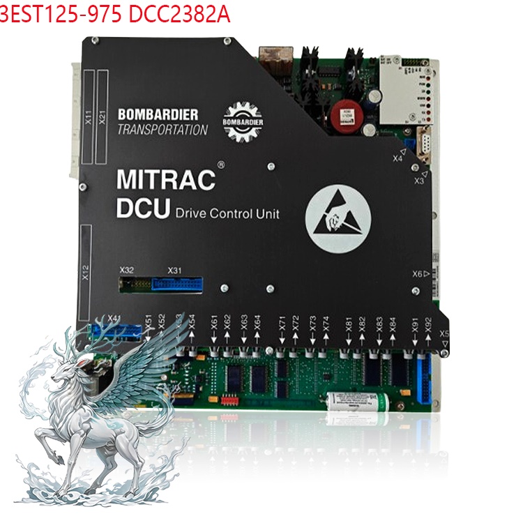
.jpg)
.jpg)


.jpg)