The EX2100E control software supports high performance and helps customers and field engineers understand, install, commission, adjust and maintain excitation control systems. The exciter software is configured and loaded through the ToolboxST application and resides in the controller. The software is represented on the ToolboxST component editor screen by control blocks, which are connected to each other to show the signal flow.
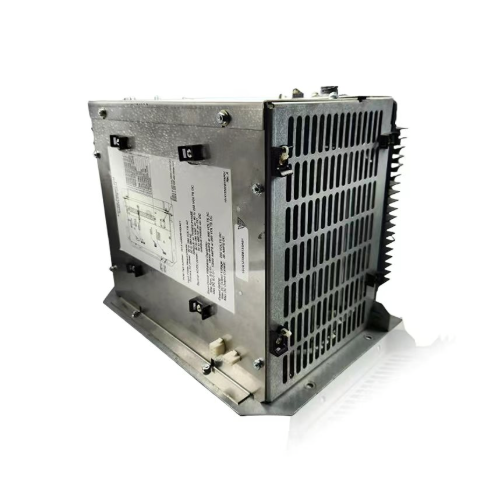
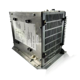
Editable controller 151X1235DG06SA03
151X1235DG06SA03 Input and output unit
Excitation control unit system 151X1235DG06SA03
Dual Control (Power Bridge Warm Backup)
The EX2100e regulator system offers a warm backup (WBU) configuration that includes dual exciter control /O and protection.
The control consists of M1 (Master One) and M2 (Master Two) with two IGBT bridges that can accept separate or shared AC input power. The control configuration can also share a common DC output circuit to the exciter field through a transfer module. M1 and M2 are independent controllers, each with automatic and manual regulator functions. Either M1 or M2 can control bridge firing, as determined by the operator. In the WBU configuration, M1 controls bridge #1 and M2 controls bridge #2.

To handle the application software, two independent Universal Controller Standalone Board Version B (UCSB) controllers with separate PCMs and output selector modules (SCM or TCM) provide DC output current for the exciter field (or SCT control winding).
The active power bridge receives gating commands from the active control (M1 or M2) and supports the full field voltage and current requirements of the exciter field when the gating circuit of the standby power bridge is inhibited. The operator has full control over selecting which of the dual power bridges is active or inactive. Bidirectional bumpless transfer between the active and inactive bridges is standard. The active master can also self-diagnose faults or missed operations and activate the standby control and power bridges without operator intervention.
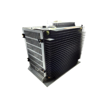
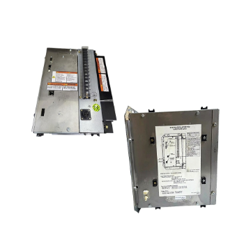
Editable controller 151X1235DG06SA03
151X1235DG06SA03 Input and output unit
Excitation control unit system 151X1235DG06SA03
Dual Control (Power Bridge Warm Backup)
The EX2100e regulator system offers a warm backup (WBU) configuration that includes dual exciter control /O and protection.
The control consists of M1 (Master One) and M2 (Master Two) with two IGBT bridges that can accept separate or shared AC input power. The control configuration can also share a common DC output circuit to the exciter field through a transfer module. M1 and M2 are independent controllers, each with automatic and manual regulator functions. Either M1 or M2 can control bridge firing, as determined by the operator. In the WBU configuration, M1 controls bridge #1 and M2 controls bridge #2.
To handle the application software, two independent Universal Controller Standalone Board Version B (UCSB) controllers with separate PCMs and output selector modules (SCM or TCM) provide DC output current for the exciter field (or SCT control winding).
The active power bridge receives gating commands from the active control (M1 or M2) and supports the full field voltage and current requirements of the exciter field when the gating circuit of the standby power bridge is inhibited. The operator has full control over selecting which of the dual power bridges is active or inactive. Bidirectional bumpless transfer between the active and inactive bridges is standard. The active master can also self-diagnose faults or missed operations and activate the standby control and power bridges without operator intervention.
The EX2100e regulator system is enclosed in a NEMA® 1/IP20 or IP21 freestanding indoor metal cabinet for floor mounting. An IP54 cabinet option is also available. The standard color of the cabinet exterior is ANSI-70 (light gray) (other colors available). The interior is galvanized steel. The equipment is designed to operate in an ambient temperature range of 0 to 40°C (32 to 104 °F). Depending on the specific application, current derating factors may apply at 50°C (122 °F).

Generator voltage
Generator active current (phase average in watts)
Generator reactive current (phase average in reactive power, VARs)
Generator frequency (current)
Slip (signal indicating rotor speed change)
• Generator power and VARs
• Generator flux (V/Hz)
• Phase angle and power factor

 ABB
ABB GE
GE HONEYWELL
 TRICONEX
 KONGSBERG
 EMERSON
 FOXBORO
 MOTOROLA
 VIBRO-METER
 ICS TRIPLEX
 WOODWARD
 BENTLY NEVADA
 OTHER
OTHER