Many products are not yet listed. Please contact us for more product
information.
If the product model differs from the displayed image, the model number
shall prevail. Please contact us for specific product images; we will arrange to
take photos in our warehouse for confirmation.
We have 76 shared warehouses worldwide, so it may sometimes take several
hours to return an accurate result. We apologize for any inconvenience. Of
course, we will respond to your inquiries as soon as possible.
Other names for 3EST13-147:
Digital Module 3EST13-147
3EST13-147 Analog Module
467 Type Socket Module 3EST13-147
I. Product Overview
The 3EST13-147 is a programmable logic controller (PLC) designed by
Bombardier Transportation specifically for rail transit signal control systems.
It belongs to the GE Fanuc/Honeywell DCC (Distributed Control Center) series
architecture. This controller is widely used in interlocking systems, ATS
(Automatic Train Control) systems, and turnout control systems for subways,
light rail, and intercity railways.
Controller Features:
Processor: 32-bit RISC architecture CPU
Program Memory: Expandable to 256K words
Scan Cycle: Typical 10~50 milliseconds
Communication Interfaces: Dual redundant Ethernet, DeviceNet,
RS-232/485
Power Supply: Dual redundant hot standby power supply module
Installation Method: DIN rail mounting, standard 19-inch rack
II. I/O Module Architecture
1. Digital Input Module (DI Module)
The digital input module receives switching signals from field devices,
converts them into low-level signals that can be processed internally by the
PLC, and provides electrical isolation.
Input Signal Type: Dry contact (passive contact) or 24VDC active signal
Isolation Method: Optocoupler isolation
Typical Point Configuration: 8 points, 16 points, 32 points
Common Terminal: All channels share a common terminal (COM), which is
divided into positive common (PNP type) and negative common (NPN type) depending
on the model.
Application Scenarios: Receiving signals from buttons, limit switches,
proximity switches, relay contacts, track circuit status, etc.
2. Digital Output Module (DO Module)
The digital output module transmits the binary control signals from the PLC
to the field actuators.
Output Type 1 – Relay Output
Contact Type: Normally Open (NO) Dry Contact
Load Capacity: AC 250VAC/5A or DC 30VDC/5A (typical)
Applicable Loads: Solenoid valves, indicator lights, relay coils,
contactors, etc.
Features: AC/DC compatible, good isolation, but slow response time
(approximately 10ms)
Output Type 2 – Transistor Output
Output Type: NPN (sink) or PNP (source)
Typical Voltage: 24VDC
Load Capacity: Approximately 0.5A per point
Applicable Loads: LED indicators, small solenoid valves, intermediate
relays, etc.
Features: Fast response time (microseconds), suitable for high-frequency
applications
Output Type 3 – Triac/SCR Output
Applicable Voltage: AC 120V/230V
Applicable Loads: AC solenoid valves, AC contactors, heaters, etc.
Features: Contactless switch, long lifespan, suitable for AC loads
3. Analog Input Module (AI Module)
Signal Types: 4-20mA current signal, 0-10V voltage signal, thermocouple
(TC), resistance temperature detector (RTD)
Accuracy: 12-bit or 13-bit A/D conversion
.jpg)
Number of Channels: Typically 4, 8, or 16 channels
Isolation: Electrical isolation between analog side and CPU side
Applications: Continuous signal acquisition such as temperature
measurement, pressure transmitters, and speed sensors
4. Analog Output Module (AO Module)
Output Signal: 4-20mA or 0-10V (Programmable Setting)
Accuracy: 12-bit or 13-bit D/A Conversion
Number of Channels: Typically 4 or 8 channels
Applications: Controlling valve opening, inverter setpoint, proportional
valve drive, etc.
III. Typical I/O Configuration (Rail Transit Interlocking System)
Module Type Typical Model Format Number of Points/Channels Voltage Rating
Remarks
Digital Input 3EST13-DIxx 8/16/32 points 24VDC Optocoupler Isolated, Dry
Contact/Active Selectable
Digital Output (Relay) 3EST13-DOxx-RL 8/16 points AC250V/DC30V Relay
Contacts Outputs
Digital Outputs (Transistors): 3EST13-DOxx-TR8/16-point 24VDC NPN/PNP
selectable
Analog Inputs: 3EST13-AIxx4/8-channel 4-20mA/0-10V, supports TC/RTD

Analog Outputs: 3EST13-AOxx4/8-channel 4-20mA/0-10V, current/voltage
adjustable
Communication Module: 3EST13-COMM—RS485/Ethernet for inter-station
communication
Power Supply Module: 3EST13-PS—24VDC/110VDC, powers I/O modules
Power Supply Module 3EST125-970 Dual AC220V input, 5V/24V output
CPU Module 3EST13-147 Main controller, for program execution
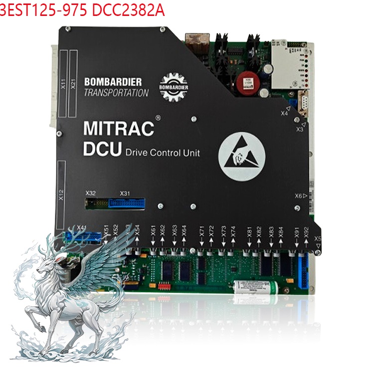
DO Module 3EST125-975 32-point relay output, drives signals and
switches
DI Module 3EST125-977 32-point digital input, acquires section and switch
status
AI Module 3EST125-976 8-channel analog input, acquires power supply
voltage
AO Module 3EST125-974 8-channel analog output, adjusts signal
brightness
High-speed counting module 3EST125-978 4-channel axle counter pulse
counting
Safety input module 3EST125-980 8-point safety input, connects to emergency
stop button
Safety output module 3EST125-979 4-point safety output, drives safety
relays
DeviceNet Module 3EST125-972 Connects to Remote I/O Stations
Ethernet Module 3EST125-981 Connects to ATS and Maintenance Terminals
IV. System Features of BOMBARDIER 3EST Series PLCs
Redundant Architecture: The 3EST13 series typically employs a dual-CPU
hot-standby redundant design to ensure high availability of the signaling
system.
Safety Level: Meets the SIL4 safety integrity level requirements for
railway signaling systems.
Rack Mounting: Modules are mounted on standard DIN rails or dedicated
racks, supporting hot-swapping.
.jpg)
Communication Interface: Supports internal bus communication and external
Ethernet/RS485 communication.
Diagnostic Functions: Each I/O module has LED status indicators (power
indicator, channel status indicator) for easy on-site troubleshooting.
Wiring and Installation Precautions
First, regarding digital input wiring:
The common terminal COM of the input module must be correctly connected
according to the output type of the field device. If using a PNP sensor (source
output, 24V high-level active signal), connect COM to 0V; if using an NPN sensor
(sinking output, 0V low-level active signal), connect COM to 24V. Incorrect
connection will cause all input points to be either always OFF or always ON.
Second, regarding digital output wiring:
The COM terminal of the relay output module must be connected to the
positive terminal of the load power supply (for DC loads) or the live wire (for
AC loads). Each output group's eight points share one COM terminal and one fuse.
If an output point is short-circuited, only the fuse in that group will burn,
without affecting other groups. The fuse is a 5A fast-blow fuse, which can be
replaced on the front panel.
Third, regarding analog module wiring:
The analog input signal lines must use shielded twisted-pair cable, with
the shield grounded at one end (grounded on the module side). Shielded cable is
also recommended for analog output lines. Do not short-circuit the input
terminals in voltage input mode; do not open-circuit the input terminals in
current input mode. When inserting the range card, ensure it is fully seated; a
"click" sound indicates it is locked.
Fourth, regarding safety modules:
Safety input and safety output modules must be used in pairs, and the drive
for the safety output must be a safety relay (such as a Siemens SIRIUS 3SK
series or Pilz PNOZ series); it cannot directly drive a regular actuator.
Diagnostic information from the safety modules must be connected to the CPU for
real-time monitoring. Any failure in a safety channel should cause the system to
enter a safe state.
Fifth, regarding module replacement:
All modules use a coded front connector design. The connector shape and pin
definitions vary depending on the module type, making it physically impossible
to insert an incorrect module. When replacing a module, first disconnect the
power, unplug the front connector of the old module, and align and insert the
connector of the new module; no rewiring is required. However, it is recommended
to record the wiring labels of each connector before disconnecting the
power.
Diagnosis and Maintenance
The 3EST13-147 CPU provides comprehensive online diagnostic functions:
Each module's front panel has three LEDs: PWR (Power), RUN (Run), and FAULT
(Fault).
The CPU polls the status of each module via the backplane bus; any module
fault will display a fault code on the CPU panel.
Detailed module diagnostic information, including channel-level fault
location, can be read via a maintenance terminal connected via Ethernet.
Digital input modules can detect open circuit faults (errors occur when the
input terminal is floating).
Digital output modules can detect load short circuits and open circuit
faults.
Analog modules can detect signal over-range faults, sensor open circuits,
etc.
All diagnostic information is timestamped for easy post-analysis
analysis.
The Bombardier 3EST13-147 PLC is a complete control platform designed
specifically for rail transit safety-critical systems. Its I/O modules cover a
full range of requirements, from basic digital to high-precision analog, and
from general I/O to SIL4 safety I/O. The fail-safe features of the relay output
module, the redundant diagnostic mechanism of the safety module, and the
multiple communication interfaces of DeviceNet/Profibus/Ethernet ensure that it
fully meets the stringent requirements of EN 50128 and EN 50129 standards for
railway signaling systems. All modules adopt the DCC series architecture, and
the front connector coding error-proof design greatly reduces the risk of field
wiring errors and improves system maintainability.
 ABB
ABB GE
GE HONEYWELL
 TRICONEX
 KONGSBERG
 EMERSON
 FOXBORO
 MOTOROLA
 VIBRO-METER
 ICS TRIPLEX
 WOODWARD
 BENTLY NEVADA
 OTHER
OTHER.jpg)
.jpg)