Many products are not yet listed. Please contact us for more product
information.
If the product model differs from the displayed image, the model number
shall prevail. Please contact us for specific product images; we will arrange to
take photos in our warehouse for confirmation.
We have 76 shared warehouses worldwide, so it may sometimes take several
hours to accurately return the information to you. We apologize for any
inconvenience. Of course, we will respond to your inquiries as soon as
possible.
Other names for 3500/22M:
Monitoring Module 3500/22M
3500/22M Communication Module
Input/Output Module 3500/22M
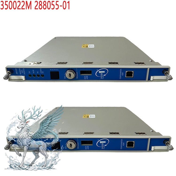
Core Positioning and Functions
Product Attributes: The core component of the Bently Nevada 3500 series
mechanical protection system, as a Transient Data Interface (TDI) module,
integrates rack interface and communication processor functions, replacing the
traditional RIM + external processor combination.
Functional Role: Serves as the interface between the 3500 system and host
computer software (such as System 1 status monitoring software), integrating the
rack interface module (RIM) and communication processor functions to achieve
steady-state/transient data acquisition, transmission, and remote
configuration.
.jpg)
Core Functions:
Data Acquisition: Supports 16-channel synchronous acquisition, 16-bit
resolution, and a sampling rate up to 100kHz, capable of capturing
steady-state/transient waveforms (such as vibration, shock events, and
start/stop data).
Interfaces and Communication:
Front Panel: USB-B port, supporting local configuration.
Network Interface: 10/100Base-TX Ethernet (RJ-45, maximum 100 meters),
100Base-FX fiber optic Ethernet (MT-RJ, maximum 400 meters multimode fiber).
Compatible with Modbus TCP/IP and Bently proprietary protocols, supporting
remote data transmission to System 1 software or PLC systems.
Signal Processing:
Input Range: -10Vdc to +10Vdc, supports Keyphasor signals and speed input
up to 20kHz (e.g., rotating machinery speed monitoring).
Data Types: Steady-state static values, transient waveform data (dynamic
data requires an optional channel activation panel).
Data Acquisition and Transmission:
Real-time acquisition of steady-state and transient dynamic data from
M-series monitors (e.g., 3500/40M, 3500/42M), transmitted to the host software
via Ethernet/fiber optic.
Supports alarm-triggered data capture: Static values are acquired at
1-second intervals 10 minutes before/1 minute after the event; static values
are acquired at 100-millisecond intervals 20 seconds before/10 seconds after
the event; waveform data is acquired at 10-second intervals 2.5 minutes before/1
minute after the alarm.
.jpg)
Configuration and Control:
Supports switching between "Run" and "Programming" modes (via key switch)
to prevent accidental configuration modifications.
The rack configuration software enables local/remote parameter settings and
supports Triple Module Redundancy (TMR) configuration to enhance system
reliability.
Event Logging and Analysis:
Memory limits the number of transient events; supports programmable
speed/time window triggered data acquisition.
Used for vibration analysis, fault diagnosis, mechanical performance
optimization, and power system stability monitoring.
Status Indication: LEDs display communication status, configuration status,
and data acquisition before/after alarms.
Event Management: Records data before/after alarms and start/stop
trajectories; supports speed-triggered sampling (e.g., 64-128 sampling
points/revolution); dynamic data storage capacity reaches 672 points.
Technical Parameters:
Electrical Characteristics: 24V DC power supply, power consumption
7.7-10.5W, operating temperature -40°C to +85°C (some models -30°C to +65°C),
protection rating IP66/IP30.
Physical Specifications: Approximately 9.5 × 4.5 × 1 inch (241 × 114 × 25
mm), weighing 0.85-1 kg, installed in rack slot 1 of the 3500 (near the power
supply).
Compatibility: Requires use with M-series monitors such as the 3500/40M and
3500/42M. Supports System 1 status monitoring software and the 3500
configuration tool.
Application Scenarios
Industry Coverage: Heavy industries such as oil and gas, power, chemical,
papermaking, steel, water treatment, and general manufacturing.
Industrial Equipment Monitoring: Vibration monitoring and health assessment
of rotating machinery such as engines, pumps, fans, and compressors.
Fault Diagnosis: Recording and analysis of transient events (such as
voltage surges and mechanical shocks) to assist in predictive maintenance.
Automation Systems: Factory automation, PLC controller data integration,
and real-time monitoring of smart grids.
.jpg)
Safety Monitoring: Real-time alarms for abnormal equipment conditions to
ensure production safety.
Typical Applications:
Rotating Equipment Monitoring: Vibration analysis of turbine, compressor,
and generator bearings/gearboxes; fault prediction (e.g., bearing defects, gear
wear).
Structural Health Monitoring: Detection of seismic activity and structural
stress changes.
Predictive Maintenance: Identification of early faults through
spectrum/trend analysis, reducing unplanned downtime.
Automation Integration: Linkage with DCS and PLC systems to achieve
closed-loop management of equipment status and control logic.
Installation and Maintenance Guide
Installation Steps:
Preparation: Power off, wear ESD protection equipment, back up rack
configuration, and record IP/network settings.
Slot Positioning: Must be installed in rack slot 1 (next to the power
supply) to avoid communication failure due to incorrect insertion into other
slots.
Wiring: Connect Ethernet/fiber optic/USB-B, ensuring grounding continuity
(insulation resistance > 10MΩ).
Configuration: Set rack mode (RUN/PROGRAM) using System 1 or 3500
configuration software, and verify data flow and event logs.
Software Configuration: Parameter settings are configured using the 3500
system configuration software, supporting remote configuration download to the
module.
Redundancy Design: Under TMR configuration, the module can compare
redundant monitor outputs, detect differences, and trigger error
indications.
Troubleshooting:
No Communication: Check IP configuration, slot location, and cable
integrity (e.g., RJ45/fiber optic interface matching).
Data Missing: Confirm channel is configured with disk access; check sensor
power supply and signal paths.
Intermittent Failure: Investigate network interference, grounding issues,
or firmware version compatibility.
Advantages and Precautions:
Performance Advantages: High-precision acquisition, multi-protocol
compatibility, anti-interference design (EMC certified), long lifespan (battery
life up to 38 years).
Usage Notes:
The module is not a protection trip path component, but its absence will
result in monitoring blind spots and loss of diagnostic capabilities.
Firmware upgrades must match the rack version to avoid compatibility
issues.

Regular maintenance is required in industrial environments (e.g., cleaning
connectors, calibrating sensors).
In summary, the 3500/22M module serves as the data hub for the Bently
Nevada machine protection system. Through high-speed, high-resolution data
acquisition and multi-protocol communication, it provides real-time status
monitoring, fault diagnosis, and predictive maintenance support for industrial
equipment, and is widely used in critical equipment reliability management
scenarios. Installation and configuration must strictly adhere to the
manufacturer's guidelines to ensure stable system operation and data
accuracy.
 ABB
ABB GE
GE HONEYWELL
 TRICONEX
 KONGSBERG
 EMERSON
 FOXBORO
 MOTOROLA
 VIBRO-METER
 ICS TRIPLEX
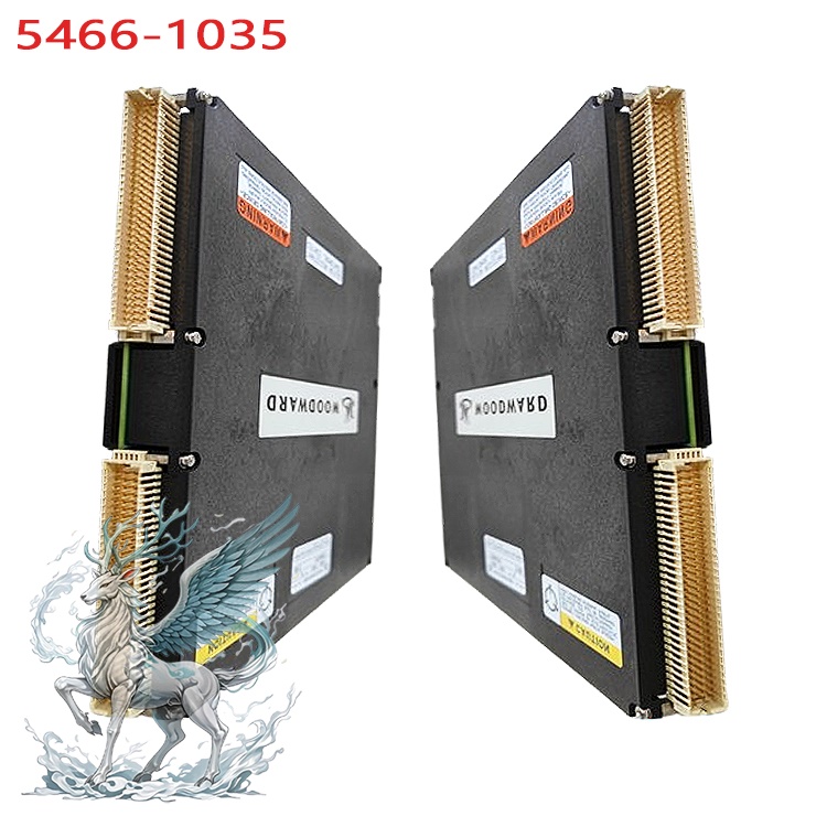
 WOODWARD
 BENTLY NEVADA
 OTHER
OTHER.jpg)
.jpg)
.jpg)


.jpg)
.jpg)